HMT056ATA-C
LCD Module User Manual
Prepared by:
Checked by:
Approved by:
Liu sanyong
Date: 2018-03-31
Date:
Date:
Rev. Descriptions
Release Date
0.1
- Preliminary Draft release
2018-03-19
0.2
Update section 3.1
2018-03-31
URL: www.topwaydisplay.com
Document Name: HMT056ATA-C
Page: 1 of 8

TOPWAY
LCD Module User Manual
HMT056ATA-C
Table of Content
1
Basic Specification ..................................................................................................................................... 3
1.1
General Specification ............................................................................................................................ 3
1.2
Block Diagram ...................................................................................................................................... 3
1.3
Terminal Function ................................................................................................................................. 4
2
Absolute Maximum Ratings....................................................................................................................... 4
3
Electrical Characteristics ........................................................................................................................... 5
3.1
DC Characteristics ................................................................................................................................ 5
3.2
AC Characteristics ................................................................................................................................ 5
4
Function Specifications ............................................................................................................................. 6
4.1
Basic Operation Function Descriptions ................................................................................................ 6
4.2
Quick Start Guide ................................................................................................................................. 7
4.3
Command Descriptions ........................................................................................................................ 7
5
Touch panel Design Precautions .............................................................................................................. 8
6
Precautions of using LCD Modules .......................................................................................................... 8
URL: www.topwaydisplay.com
Document Name: HMT056ATA-C
Page: 2 of 8
TOPWAY
LCD Module User Manual
HMT056ATA-C
1 Basic Specification
TOPWAY HMT056ATA-C is a Smart TFT Module with 32bit MCU on board. Its graphics engine provides
numbers of outstanding features. It supports TOPWAY TML 2.4 for preload and pre-design display
interface that simplify the host operation and development time. Suitable for industry control,
instrumentation, medical electronics, power electric equipment applications.
1.1 General Specification
Screen Size(Diagonal) :
5.6”
Resolution :
640(RGB) x480
Color Depth :
65k color (16bit)
Pixel Configuration :
RGB Stripe
Display Mode :
Transmissive / Normal White
Viewing Direction :
6H (*1) (gray-scale inverse)
12H (*2)
Outline Dimension :
144.8 x 110.2 x 21.6 (max)(mm)
(see attached drawing for details)
Active Area :
112.9 x 84.67 (mm)
Backlight :
LED
Command I/F:
RS-232C
Project Download:
by PC
Operating Temperature :
-20 ~ +70°C
Storage Temperature :
-30 ~ +80°C
Note:
*1. For saturated color display content (eg. pure-red, pure-green, pure-blue, or pure-colors-combinations).
*2. For “color scales” display content.
*3. Color tone may slightly change by Temperature and Driving Condition.
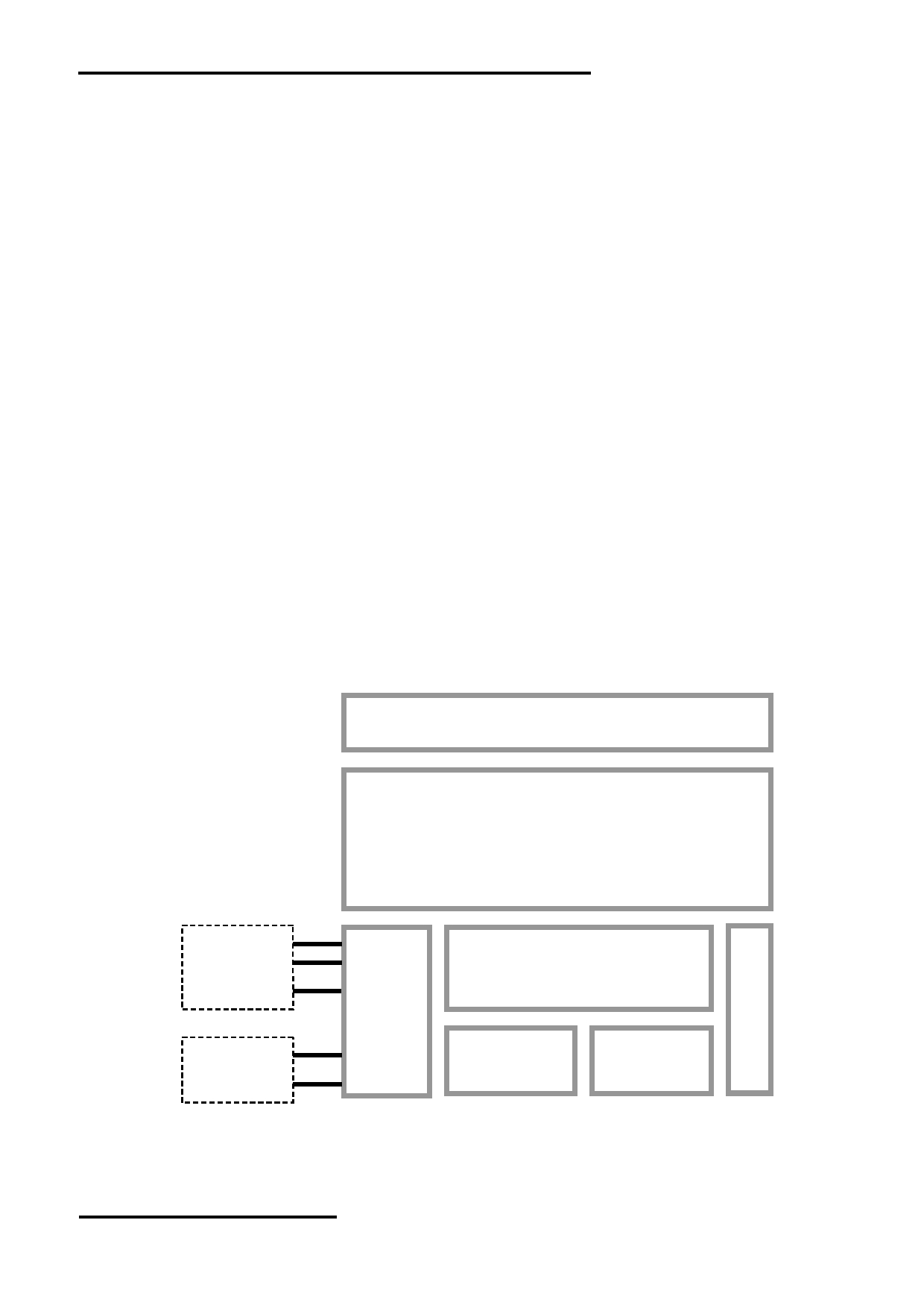
1.2 Block Diagram
Touch Panel
5.6” TFT
640 x 480 pixels
K1,K3
RTS(BUSY)
TX, RX
Display Function Controller
VCC, GND
with RTC
K2
D-, D+
Flash
Memory
RAM
VUSB, GND
URL: www.topwaydisplay.com
Document Name: HMT056ATA-C
Page: 3 of 8

TOPWAY
LCD Module User Manual
HMT056ATA-C
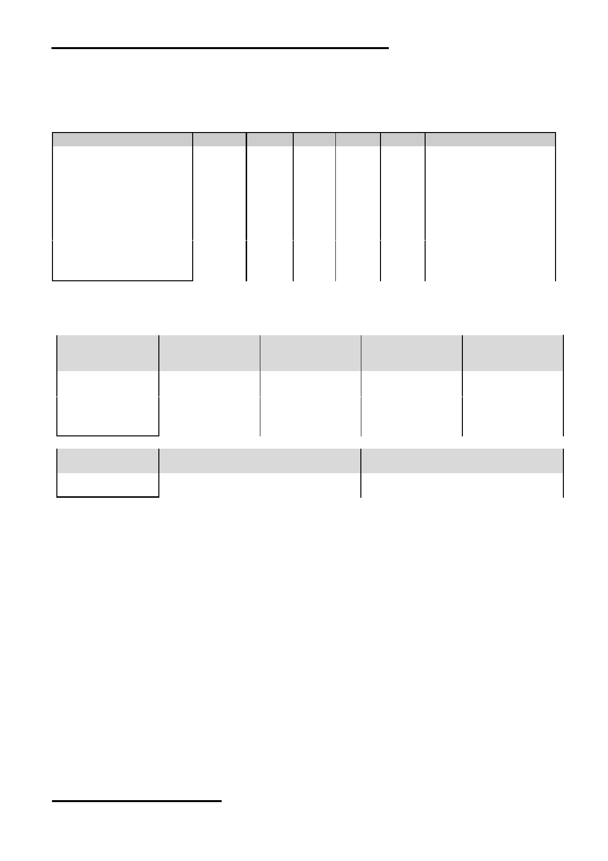
1.3 Terminal Function
RS232 Interface Terminal (K1)
Pin No.
Pin Name
I/O Descriptions
1,2,3
VCC
P
Power supply (6~26 V)
4
NC
--
--
5
RX
I
Data Input
(eg. to PC’s RS-232C pin3 <9pin D-connector>)
6
TX
O
Data output
(eg. to PC’s RS-232C pin2 <9pin D-connector>)
7
RTS(BUSY)
O
Request To Send (could function as busy BUSY signal)
(eg. to PC’s RS-232C pin8 <9pin D-connector>)
8,9,10
GND
P
Ground, (0V)
Note.
*1. User data and commands transfer through this terminal.
*2. HW hand shake is suggested.
RS232 Interface Terminal (K3)
Pin No.
Pin Name
I/O Descriptions
1,2
VCC
P
Power supply (6~26 V)
3
RTS(BUSY)
--
Request To Send (could function as busy BUSY signal)
(eg. to PC’s RS-232C pin8 <9pin D-connector>)
4
TX
O
Data output
(eg. to PC’s RS-232C pin2 <9pin D-connector>)
5,6
RX
I
Data Input
(eg. to PC’s RS-232C pin3 <9pin D-connector>)
7,8
GND
P
Ground, (0V)
Note.
*1. User data and commands transfer through this terminal.
*2. HW hand shake is suggested.
USB Interface Terminal (K2)
Pin No.
Pin Name
I/O Descriptions
1
VUSB
P
Power supply(5.0 V)
2
D-
I/O
USB DATA negative signal
3
D+
I/O
USB DATA positive signal
4
NC
--
No connection,leave open
5
GND
P
Ground, (0V)
Note.
*1. TML files and image files preload through this terminal
*2. Standard “USB-drive” functions provided
*3. During the files transfer, all others display functions will be suspended
2 Absolute Maximum Ratings
Items
Symbol
Min.
Max.
Unit
Condition
Power Supply voltage
V CC
-0.3
26.0
V
Operating Temperature
T OP
-20
70
℃
No Condensation
Storage Temperature
T ST
-30
80
℃
No Condensation
Note:
*1. This rating applies to all parts of the module and should not be exceeded.
*2. The operating temperature only guarantees operation of the circuit. The contrast, response speed,
and the other specification related to electro-optical display quality is determined at the room temperature, T OP =25 ℃
*3. Ambient temperature when the backlight is lit (reference value)
*4. Any Stresses exceeding the Absolute Maximum Ratings may cause substantial damage to the device. Functional
operation of this device at other conditions beyond those listed in the specification is not implied and prolonged
exposure to extreme conditions may affect device reliability.
URL: www.topwaydisplay.com
Document Name: HMT056ATA-C
Page: 4 of 8
TOPWAY
LCD Module User Manual
HMT056ATA-C
3 Electrical Characteristics
3.1 DC Characteristics
GND=0V, VCC=12.0V,T OP =25 ℃
Items
Symbol
MIN.
TYP.
MAX.
Unit Applicable Pin/FUNC
Operating Voltage
V CC
6.0
12.0
26.0
V
VCC
RxD Input MARK(1)
V RxDM
-3.0
-
-15.0
V
RxD
RxD Input SPACE(0)
V RxDS
+3.0
-
+15.0
V
RxD
TxD Output MARK(1)
V TxDM
-3.0
-
-15.0
V
TxD
TxD Output SPACE(0)
V TxDS
+3.0
-
+15.0
V
TxD
RTS(BUSY) Output High
V TxH
-3.0
-
-15.0
V
RTS(BUSY)
RTS(BUSY) Output Low
V TxL
+3.0
-
+15.0
V
RTS(BUSY)
Operating Current
I CC
-
240
500
mA
VCC (*1)
Operating Current (USB)
I VUSB
-
200
-
mA
VUSB
Battery Supply Current
I BAT
-
6
-
uA
(*2)
Note.
*1. Normal display condition
3.2 AC Characteristics
Items
JP1,JP7=close,
JP1,JP8=close,
JP1,JP8= open,
JP1,JP7= open,
JP2,JP8=open
JP2,JP7=open
JP2,JP7= close
JP2,JP8= close
(factory default)
Start bit
1
1
1
1
Data bit
8
8
8
8
Parity bit
None
None
Even
Odd
Stop bit
1
1
1
1
Baud Rate(*1)
115200 bps
9600 bps
115200 bps
115200 bps
Items
JP3=close, JP4=open
JP3= open, JP4=close
(factory default)
Serial Data
busy
Xon/Xoff
Flow Control
Note.
*1.Baud Rate (1200bps ~ 115200bps) could be adjusted by software.
URL: www.topwaydisplay.com
Document Name: HMT056ATA-C
Page: 5 of 8
TOPWAY
LCD Module User Manual
HMT056ATA-C
4 Function Specifications
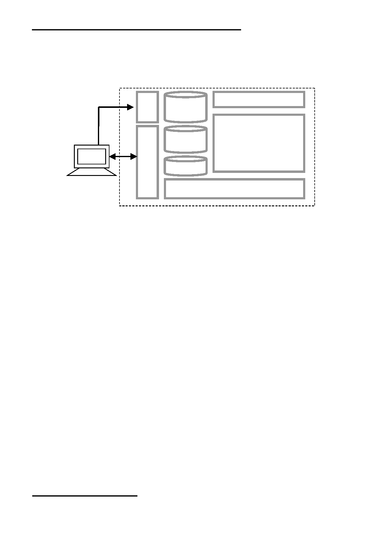
4.1 Basic Operation Function Descriptions
HMT056ATA-C
Touch Panel
TML files
Picture files
ICONS files
Custom
Memories
TFT Display
HOST
PC
VP variables
Control and Draw Engine
- TML files, Picture files, ICON files are stored inside FLASH memory area.
They are preloaded to HMT056ATA-C for stand alone interface use.
- Those files are preloaded via USB interface as an USB drive.
- All the interface flow and the touch response are based on the preloaded TML files
- VP variables memory is inside RAM area,
it provides real time access via UART by the HOST or display onto the TFT by TML file.
- Custom Memories are inside FLASH memory area
It can be accessed via UART interface by the HOST.
- Control and Draw Engine executes HOST commands and response respectively
- It also reports the real time Touch Key number to the HOST
URL: www.topwaydisplay.com
Document Name: HMT056ATA-C
Page: 6 of 8
TOPWAY
LCD Module User Manual
HMT056ATA-C
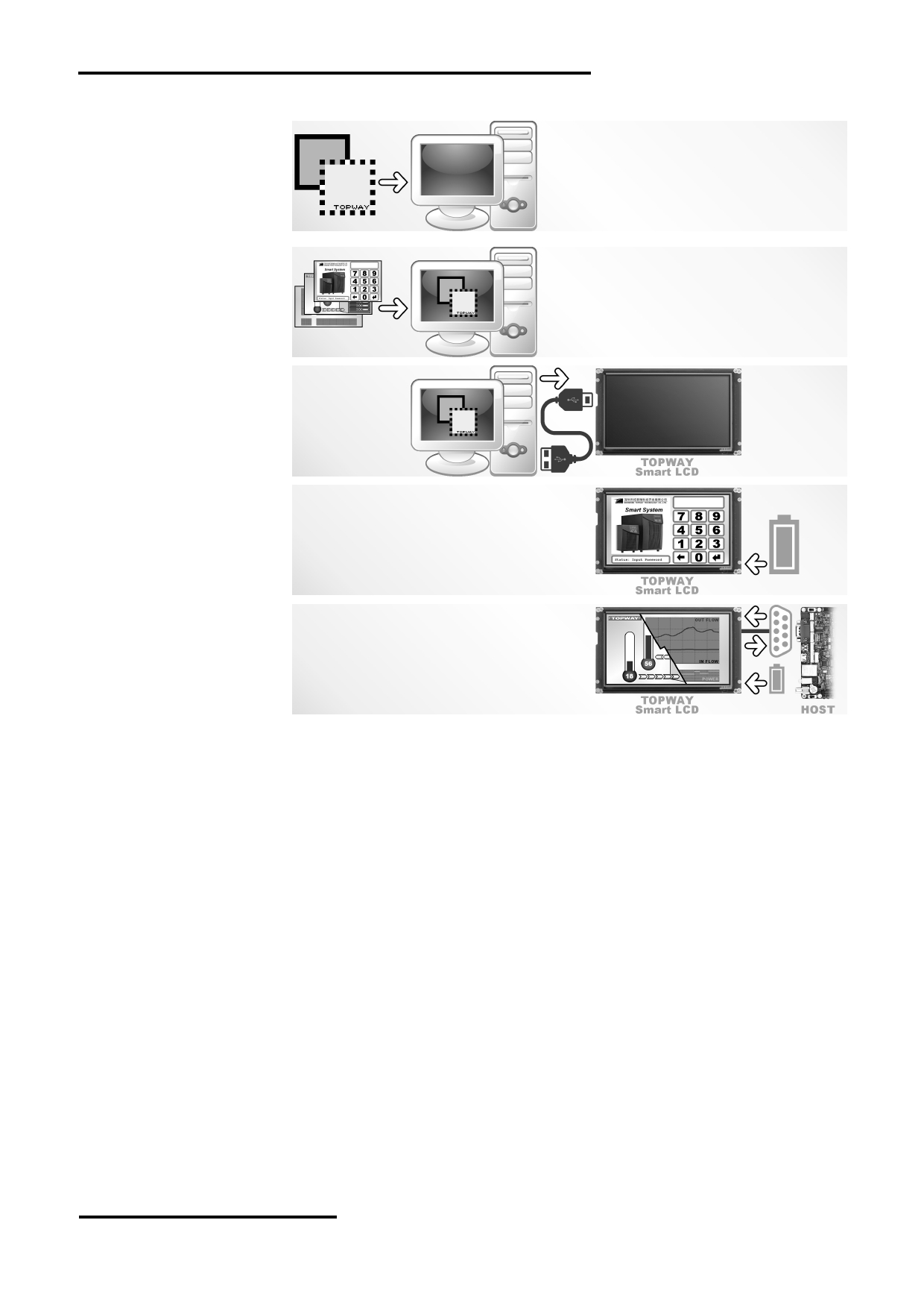
4.2 Quick Start Guide
1.
Install TOPWAY
Graphics Editor
Import pictures
2. design UI flow
3.
Download to
Smart LCD
4. power on &
display
Connect to
5.
host Show
real time
data
4.3 Command Descriptions
Please refer to “SMART LCD Command Manual”.
URL: www.topwaydisplay.com
Document Name: HMT056ATA-C
Page: 7 of 8
TOPWAY
LCD Module User Manual
HMT056ATA-C
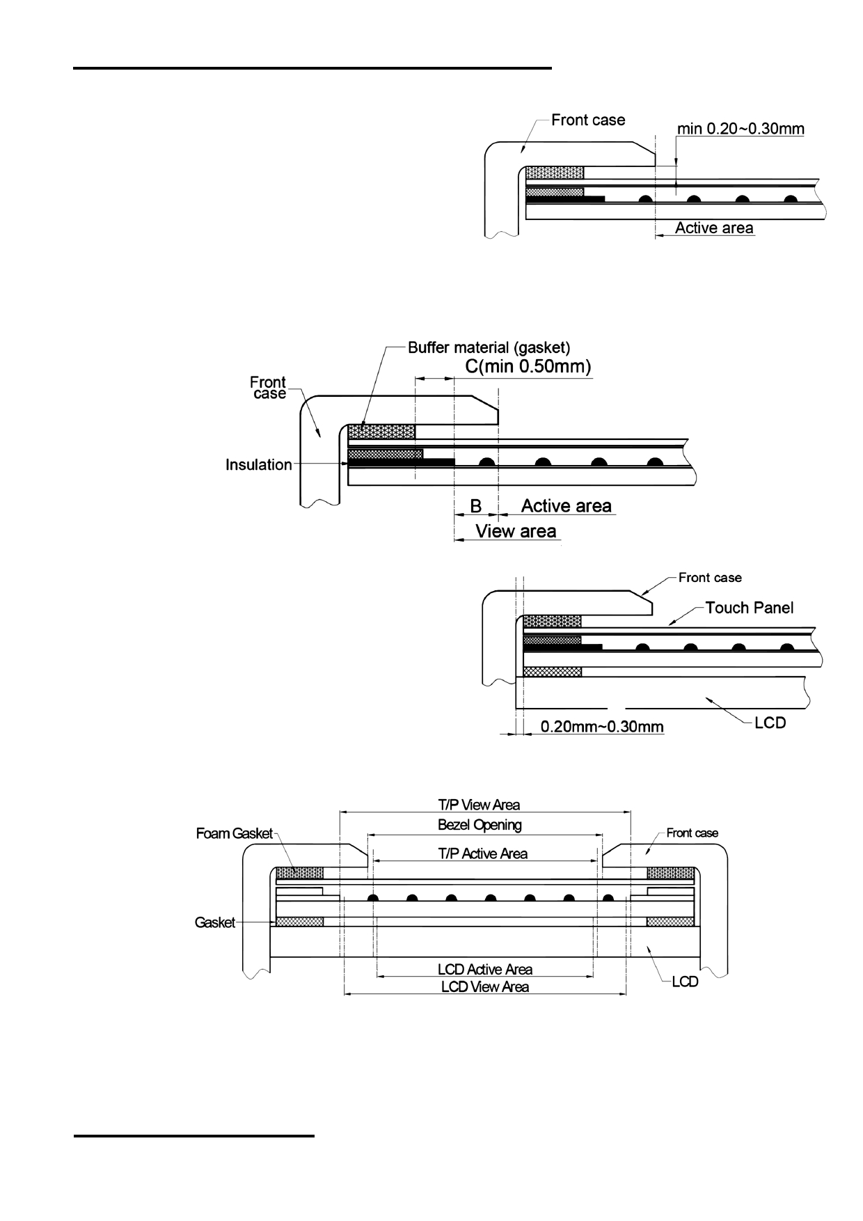
5 Touch panel Design Precautions
1. It should prevent front case
touching the touch panel
Active Area (A.A.) to prevent
abnormal touch.
It should left gab (e.g.
0.2~0.3mm) in between.
2. Outer case design should take care about the area outside the A.A.
Those areas contain circuit wires which is having different thickness. Touching those areas could de-
form the ITO film. As a result case the ITO cold be damaged and shorten its lifetime.
It is suggested to protect those areas with gasket (between the front case and the touch panel).
The suggested figures are B≥0.50mm; C≥0.50mm 。
3. The front case side wall should keep space
(e.g. 0.2 ~ 0.3mm) from the touch panel.
4. In general design,
touch panel V.A. should be bigger than the LCD V.A.
and touch panel A.A. should be bigger than the LCD A.A.
6 Precautions of using LCD Modules
Please refer to "LCD-Module-Design-Handling-Precaution.pdf".
URL: www.topwaydisplay.com
Document Name: HMT056ATA-C
Page: 8 of 8