LM1076DCW
LCD Module User Manual
Prepared by:
Checked by:
Approved by:
Li Yinyang
Date: 2016-08-04
Date:
Date:
Rev. Descriptions
Release Date
0.1
Preliminary release
2016-08-04
URL: www.topwaydisplay.com
Document Name :LM1076DCW-Manual-Rev0.1
Page: 1 of 12

TOPWAY
LCD Module User Manual
LM1076DCW
Table of Content
1. Basic Specifications ............................................................................................................... 3
1.1
Display Specifications ........................................................................................................ 3
1.2
Mechanical Specifications .................................................................................................. 3
1.3
Block Diagram ..................................................................................................................... 3
1.4
Terminal Functions ............................................................................................................. 4
2. Absolute Maximum Ratings ................................................................................................... 5
3. Electrical Characteristics ....................................................................................................... 5
3.1
DC Characteristics .............................................................................................................. 5
3.2
LED Backlight Circuit Characteristics ............................................................................... 5
3.3
AC Characteristics .............................................................................................................. 6
4. Function specifications .......................................................................................................... 7
4.1
Adjusting the Display Contrast .......................................................................................... 7
4.2
Resetting the LCD module .................................................................................................. 7
4.3
Display Commands ............................................................................................................. 8
5. Design and Handling Precaution ......................................................................................... 12
URL: www.topwaydisplay.com
Document Name :LM1076DCW-Manual-Rev0.1
Page: 2 of 12

TOPWAY
LCD Module User Manual
LM1076DCW
1. Basic Specifications
1.1 Display Specifications
1) LCD Display Mode
: FSTN, Positive, Transflective
2) Display Color
: Display Data = “1” : Dark Gray(*1)
: Display Data = “0” : Light Gray(*2)
3) Viewing Angle
: 6H
4) Driving Method
: 1/128 duty, 1/12 bias
5) Backlight
: White LED backlight
Note:
*1. Color tone may slightly change by Temperature and Driving Condition.
*2. The Color is defined as the inactive / background color
*3. Fine Contrast adjustment function is necessary in the application design for optimal display result
1.2 Mechanical Specifications
1) Outline Dimension
: 79.5 x 64.0 x 10.1MAX (mm)
(See attached Outline Drawing for details)
1.3 Block Diagram
BLA
Backlight Circuit
LCD Panel
240 × 128Pixels
VDD
VSS
SI, SCL, A0
UC1698 or equivalent
/CS1, /RES
URL: www.topwaydisplay.com
Document Name :LM1076DCW-Manual-Rev0.1
Page: 3 of 12

TOPWAY
LCD Module User Manual
LM1076DCW
1.4 Terminal Functions
Pin No.
PIN
I/O
Descriptions
(K1&K2) Name
Serial mode
1
VSS
Power Negative power supply,0V
2
VDD
Power Positive power supply
3
SI
Input Serial data input
4
SCL
Input Serial clock input
Register Select
5
A0
Input A0 = H, Transferring the Display Data
A0 = L, Transferring the Control Data
6
Reset signal
/RES
Input /RES = L, Initialization is executed
/RES = H, Normal running.
Chip Select
7
/CS1
Input /CS1=L, enable access to the LCD module
/CS1=H, disable access to the LCD module
8
BLA
Power Positive power for LED backlight
URL: www.topwaydisplay.com
Document Name :LM1076DCW-Manual-Rev0.1
Page: 4 of 12

TOPWAY
LCD Module User Manual
LM1076DCW
2. Absolute Maximum Ratings
Items
Symbol
Min.
Max.
Unit Condition
Supply Voltage
V DD
-0.3
+3.6
V
V SS = 0V
Input Voltage
V IN
-0.3
V DD +0.3
V
V SS = 0V
Operating Temperature
T OP
-20
+70
C
No Condensation
Storage Temperature
T ST
-30
+80
C
No Condensation
Cautions:
Any Stresses exceeding the Absolute Maximum Ratings may cause substantial damage to the device. Functional
operation of this device at other conditions beyond those listed in the specification is not implied and prolonged exposure
to extreme conditions may affect device reliability.
3. Electrical Characteristics
3.1 DC Characteristics
V SS =0V, V DD =3.3V, T OP =25 C
Items
Symbol
MIN.
TYP.
MAX.
Unit
Condition /
Application Pin
Operating Voltage
V DD
2.7
3.3
3.465
V
VDD
Input High Voltage
V IH
0.8xV DD
-
V DD
V
/RES, /CS1, A0,
Input Low Voltage
V IL
V SS
-
0.2xV DD
V
SI,SCL
Operating Current
I DD
-
1.2
3
mA
VDD
3.2 LED Backlight Circuit Characteristics
V SS =0V, BLA=3.3V, T OP =25 C
Items
Symbol
MIN.
TYP.
MAX.
Unit
Applicable Pin
Forward Voltage
BLA
-
3.3
-
V
BLA
Forward Current
I BLA
-
90
100
mA
BLA
Cautions:
Exceeding the recommended driving current could cause substantial damage to the backlight and shorten its lifetime.
BLA
VSS
No. of LED = 5pcs
URL: www.topwaydisplay.com
Document Name :LM1076DCW-Manual-Rev0.1
Page: 5 of 12

TOPWAY
LCD Module User Manual
LM1076DCW
3.3 AC Characteristics
3.3.1 4-Write serial
SCL
SI
V SS =0V, V DD =3.3V, T OP =25 C
Item
Symbol
MIN.
TYP.
MAX.
Unit
Address setup time (A0)
tass8
5
-
-
ns
Address hold time (A0)
tahs8
5
-
-
ns
System cycle time
tcys8
91
-
-
ns
SCLK low pulse width
tlpws8
26
-
-
ns
SCLK high pulse width
thpws8
26
-
-
ns
SDA data setup time
tdss8
20
-
-
ns
SDA data hold time
tdhs8
5
-
-
ns
Chip select setup time
tcssas8
7
-
-
ns
Chip select hold time
tcshs8
7
-
-
ns
`
Note:
*1. Input signal rise/fall time should be less than 15ns .
*2. CL=100pF
*3.All timing is using 20% and 80% of VDD as the reference.
3.3.2 Reset Timing
V SS =0V, V DD =3.3V, T OP =25 C
Item
Symbol
MIN.
TYP.
MAX.
Unit
Reset LOW pulse width
trw
4
-
-
Reset to WR pulse delay
tRD
10
-
-
ms
Note:
*1.All timing is using 20% and 80% of VDD as the reference.
URL: www.topwaydisplay.com
Document Name :LM1076DCW-Manual-Rev0.1
Page: 6 of 12
TOPWAY
LCD Module User Manual
LM1076DCW
4. Function specifications
4.1 Adjusting the Display Contrast
This LCD module equipped with latest digital contrast adjustment function.
Its display contrast could be adjusted by MCU command.
(please see the command tables for details)
It is recommended to provide a contrast adjustment interface for end-user,
where the best display result could meet the individual preference in mass production.
4.2 Resetting the LCD module
The LCD module should be initialized by using /RES terminal.
While turning on the VDD and VSS power supply, maintain /RES terminal at LOW level. After the
power supply stabilized, release the reset terminal (/RES=HIGH)
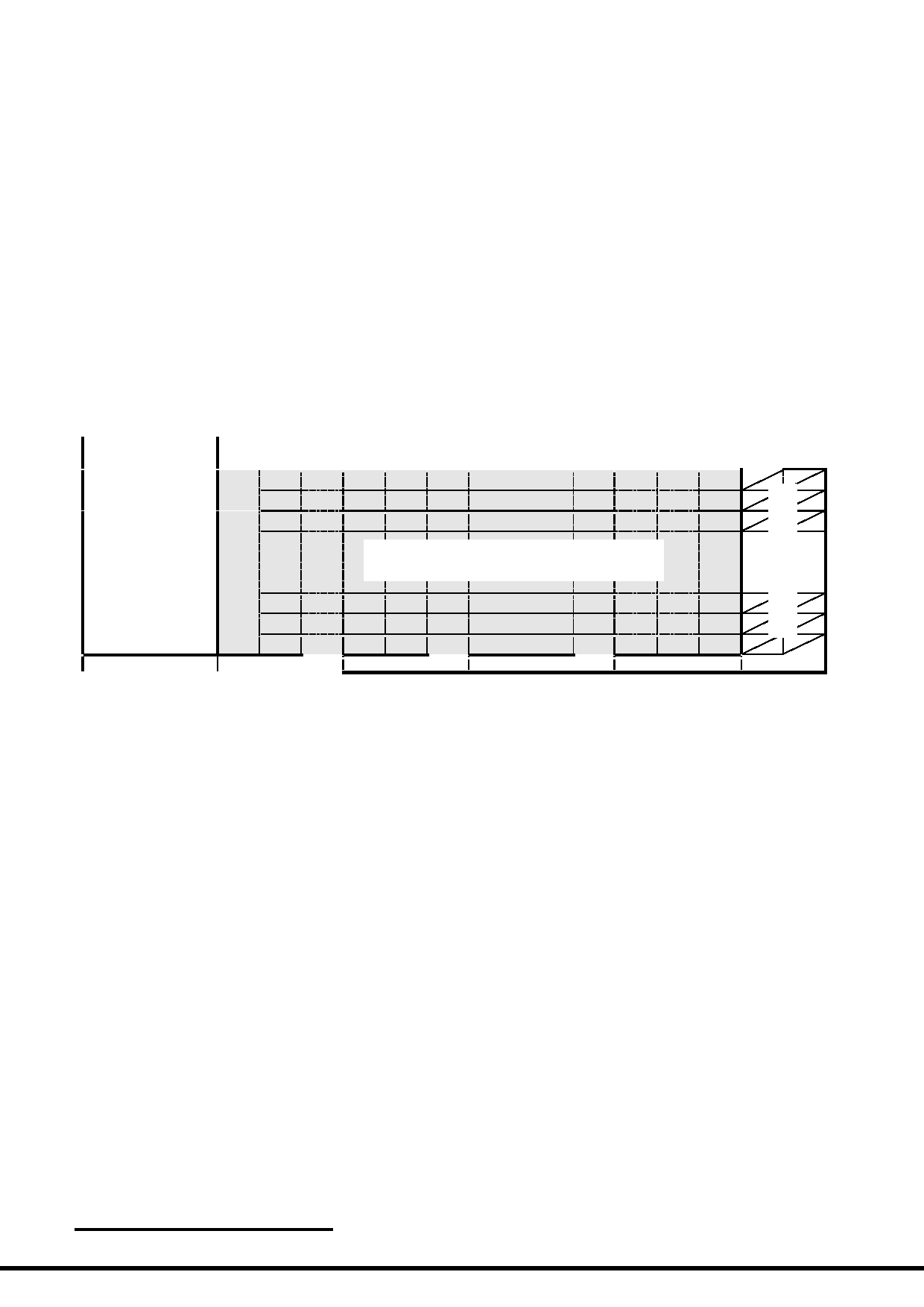
4.2.1 Display Memory Map
ROW
no.
LCD Display (front view)
1 st
2 nd
3 rd
:
240 x 128 pixels
126 th
127 th
128 th
Column Address
00h
01h
4fh
50h
Note:
*1. This mono LCM is driven by a color LCD driver.
Every three dots are being driven by R G B segment driver.
*2. The above is based on:
- 4R4G4B setting, each dot will be driven by 4bit; LC[7:6]=0:1, DC[4]=1
- Mirror Y direction; LC[2]=0
- Normal X direction; LC[1]=1
- Color Mapping as BGR; LC[5]=0
*3. For details please refer to UC1698 datasheet
URL: www.topwaydisplay.com
Document Name :LM1076DCW-Manual-Rev0.1
Page: 7 of 12

TOPWAY
LCD Module User Manual
LM1076DCW
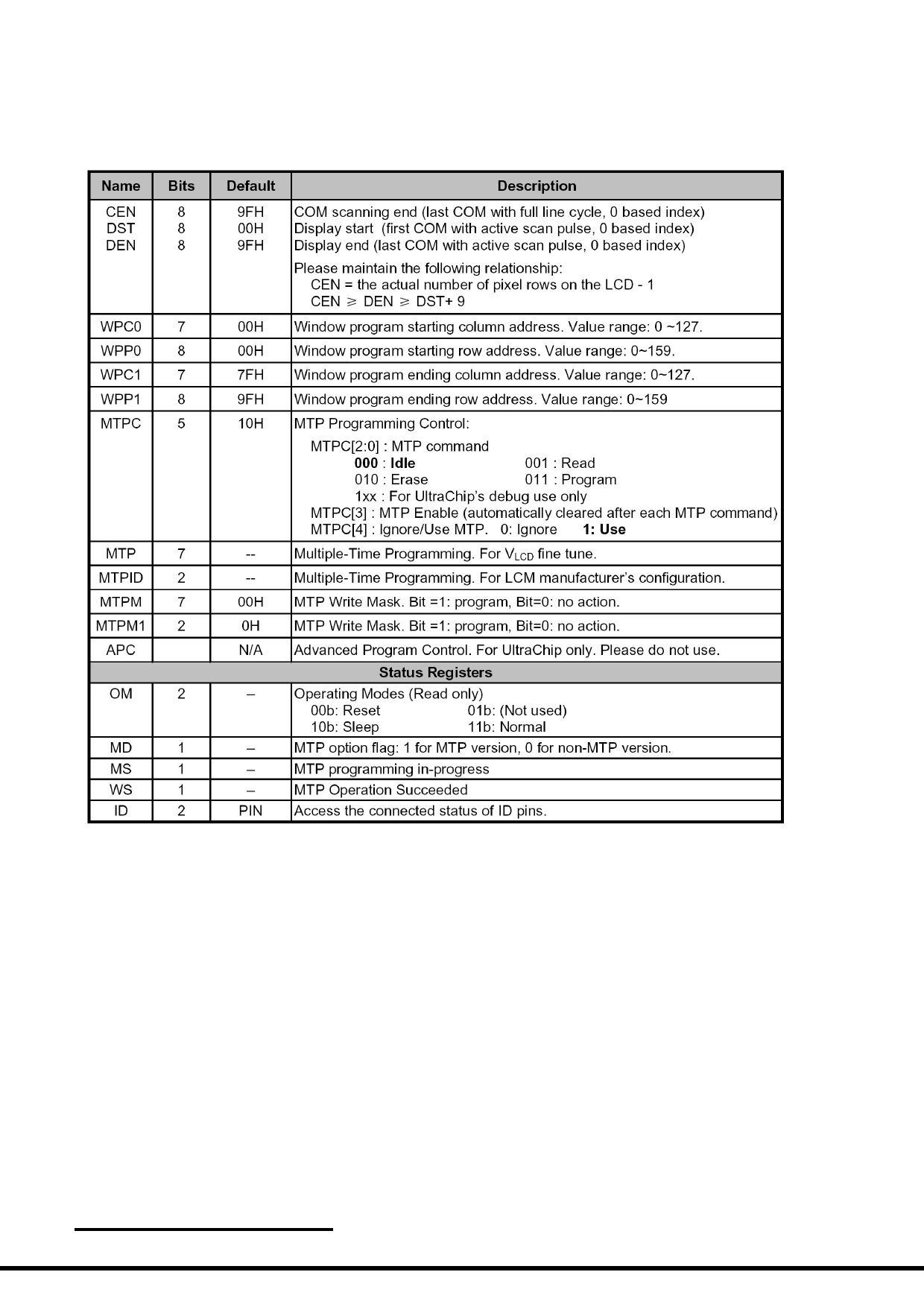
4.3 Display Commands
The LCD module contains register, which control the operation. These register can be modified by commands.
The following table is a summary of the control registers, their meaning and their default value.
4.3.1 Register Table
URL: www.topwaydisplay.com
Document Name :LM1076DCW-Manual-Rev0.1
Page: 8 of 12

TOPWAY
LCD Module User Manual
LM1076DCW
Register Table (continue)
URL: www.topwaydisplay.com
Document Name :LM1076DCW-Manual-Rev0.1
Page: 9 of 12
TOPWAY
LCD Module User Manual
LM1076DCW
Register Table (continue)
Note: Please refer to UC1698 data sheet for details
URL: www.topwaydisplay.com
Document Name :LM1076DCW-Manual-Rev0.1
Page: 10 of 12

TOPWAY
LCD Module User Manual
LM1076DCW
4.3.2 Command Table
The following is the list of host command supported.
Note:
Please refer to UC1698 data sheet for details
URL: www.topwaydisplay.com
Document Name :LM1076DCW-Manual-Rev0.1
Page: 11 of 12

TOPWAY
LCD Module User Manual
LM1076DCW
5. Design and Handling Precaution
Please refer to "LCD-Module-Design-Handling-Precaution.pdf".
URL: www.topwaydisplay.com
Document Name :LM1076DCW-Manual-Rev0.1
Page: 12 of 12