LM240160DFW
LCD Module User Manual
Prepared by:
Checked by:
Approved by:
Lincaian
Date: 2009-04-27
Date:
Date:
Rev. Descriptions
Release Date
0.1
Prelimiay release
2007-11-06
0.2
Update BIAS setting
2007-11-12
0.3
Add EPMRD function discription
2009-04-27
URL: www.topwaydisplay.com
Document Name: LM240160DFW-Manual-Rev0.3
Page: 1 of 11

TOPWAY
LCD Module User Manual
LM240160DFW
Table of Content
1. Basic Specifications .............................................................................................................. 3
1.1
Display Specifications ............................................................................................................................................ 3
1.2
Mechanical Specifications ...................................................................................................................................... 3
1.3
Block Diagram ........................................................................................................................................................ 3
1.4
Terminal Functions ................................................................................................................................................. 3
2. Absolute Maximum Ratings .................................................................................................. 4
3. Electrical Characteristics ...................................................................................................... 4
3.1
DC Characteristics ................................................................................................................................................. 4
3.2
LED Backlight Circuit Characteristics ..................................................................................................................... 4
3.3
AC Characteristics ................................................................................................................................................. 5
4. Function Specifications ........................................................................................................ 7
4.1
Basic Setting .......................................................................................................................................................... 7
4.2
Resetting the LCD module ..................................................................................................................................... 7
4.3
Display Memory Map ............................................................................................................................................. 7
4.4
Commands ............................................................................................................................................................. 8
4.5
Basic Operating Sequence (example) .................................................................................................................. 10
5. Design and Handling Precaution ........................................................................................ 11
URL: www.topwaydisplay.com
Document Name: LM240160DFW-Manual-Rev0.3
Page: 2 of 11
TOPWAY
LCD Module User Manual
LM240160DFW
1. Basic Specifications
1.1 Display Specifications
1) LCD Display Mode
: STN-BLUE, Negative, Transmissive
2) Display Color
: Display Data = “1” : Light Gray (*1)
: Display Data = “0” : Dark Blue (*2)
3) Viewing Angle
: 6H
4) Driving Method
: 1/160 duty, 1/12 bias
5) Back Light
: White LED backlight
Note:
*1. Color tone may slightly change by Temperature and Driving Condition.
*2. The Color is defined as the inactive / background color
1.2 Mechanical Specifications
1) Outline Dimension
: 92.7 x 72.0 x 9.05MAX
(See attached Outline Drawing for details)
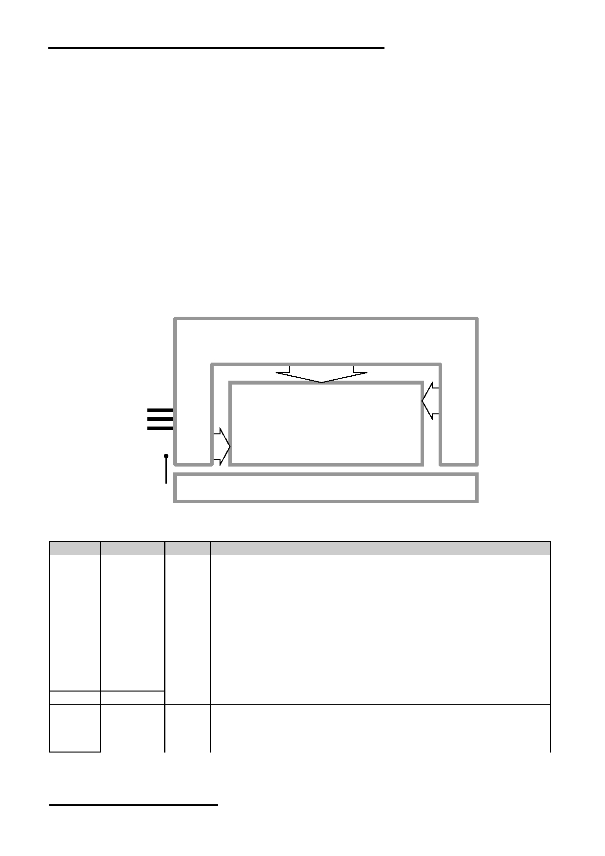
1.3 Block Diagram
ST7529
or
equivalent
COM79
:
DB0 ~ DB7
LCD Panel
COM0
RS, /WR, /RD
/CS, /RST
240 x 160 pixels
COM80
VDD
:
VSS
COM159
Back Light Circuit
BLA
1.4 Terminal Functions
Pin No. Pin Name
I/O
Descriptions
1
VDD
Power Positive Power Supply
2
VSS
Power 0V Supply, Ground (0V)
3
/CS
Input Chip Select
/CS=LOW : Data IO is enabled
4
RS
Input Register Select
RS=HIGH: data on DB0 to DB7 is display data
RS=LOW: data on DB0 to DB7 is control data
5
/WR
Input Write enable input, active LOW
6
/RD
Input Read enable input, active LOW
7
DB0
I/O
Bi-directional data bus:
:
:
14
DB7
15
/RST
Input Reset:
/RST=LOW: Initialization is executed
/RST=HIGH: Normal
16
BLA
Power Backlight Positive Power Supply
URL: www.topwaydisplay.com
Document Name: LM240160DFW-Manual-Rev0.3
Page: 3 of 11

TOPWAY
LCD Module User Manual
LM240160DFW
2. Absolute Maximum Ratings
Items
Symbol
Min.
Max.
Unit Condition
Supply Voltage
V DD
-0.3
+4.0
V
V SS = 0V
Input Voltage
V IN
-0.3
V DD +0.3
V
V SS = 0V
Operating Temperature
T OP
-20
+70
C
No Condensation
Storage Temperature
T ST
-30
+80
C
No Condensation
Cautions:
Any Stresses exceeding the Absolute Maximum Ratings may cause substantial damage to the device. Functional
operation of this device at other conditions beyond those listed in the specification is not implied and prolonged exposure
to extreme conditions may affect device reliability.
3. Electrical Characteristics
3.1 DC Characteristics
V SS =0V, V DD =3.3V, T OP =25 C
Items
Symbol
MIN.
TYP
MAX.
Unit Condition /
.
Application Pin
Operating Voltage
V DD
3.1
3.3
3.6
V
VDD
Input High Voltage
V IH
0.8xV DD
-
V DD
V
/RST, /CS, RS, /WR, /RD,
Input Low Voltage
V IL
0
-
0.2xV DD
V
DB0~DB7
Operating Current
I DD
-
1.5
7.0
mA VDD
3.2 LED Backlight Circuit Characteristics
V SS =0V, If BLA =60mA, T OP =25 C
Items
Symbol
MIN.
TYP.
MAX.
Unit Applicable Pin
Forward Voltage
Vf BLA
-
3.3
-
V
VLED-
Forward Current
If BLA
-
85
110
mA VLED-
Cautions:
Exceeding the recommended driving current could cause substantial damage to the backlight and shorten its lifetime.
BLA
VSS
No. of LED = 5pcs
URL: www.topwaydisplay.com
Document Name: LM240160DFW-Manual-Rev0.3
Page: 4 of 11
TOPWAY
LCD Module User Manual
LM240160DFW
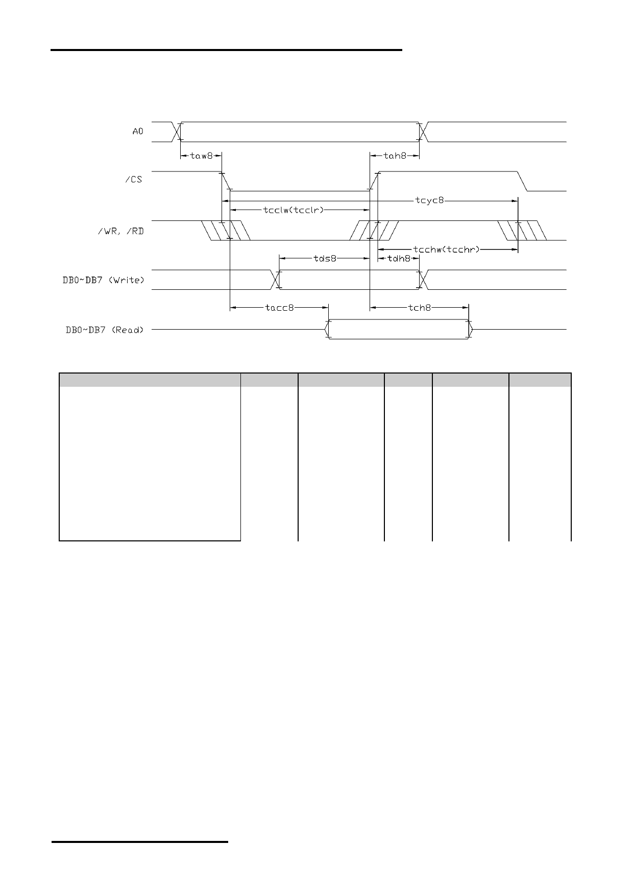
3.3 AC Characteristics
3.3.1 8080 Mode System Bus Timing
V SS =0V, V DD =3.3V, T OP =25 C
Item
Symbol
MIN.
TYP.
MAX.
Unit
System cycle time
tcyc8
285
-
-
ns
Address setup time (A0)
taw8
29
-
-
ns
Address hold time (A0)
tah8
29
-
-
ns
Control LOW pulse width (/WR)
tcclw
143
-
-
ns
Control LOW pulse width (/RD)
tcclr
143
-
-
ns
Control HIGH pulse width (/WR)
tcchw
143
-
-
ns
Control HIGH pulse width (/RD)
tcchr
143
-
-
ns
Data setup time
tds8
100
-
-
ns
Data hold time
tdh8
29
-
-
ns
/RD access time (*2)
tacc8
-
-
57
ns
Output disable time (*2)
tch8
-
-
38
ns
Note:
*1. Input signal rise/fall time should be less than 12ns
*2. CL=100pF
URL: www.topwaydisplay.com
Document Name: LM240160DFW-Manual-Rev0.3
Page: 5 of 11

TOPWAY
LCD Module User Manual
LM240160DFW
3.3.2 6800 Mode System Bus Timing
V SS =0V, V DD =3.3V, T OP =25 C
Item
Symbol
MIN.
TYP.
MAX.
Unit
System cycle time
tcyc6
285
-
-
ns
Address setup time
taw6
29
-
-
ns
Address hold time
tah6
29
-
-
ns
Enable High pulse width (Read)
tewhr
143
-
-
ns
Enable High pulse width (Write)
tewhw
143
-
-
ns
Enable Low pulse width (Read)
tewlr
143
-
-
ns
Enable Low pulse width (Write)
tewlw
143
-
-
ns
Data setup time
tds6
214
-
-
ns
Data hold time
tdh6
20
-
-
ns
Output disable time (*2)
toh6
-
-
43
ns
Access time (*2)
tacc6
-
-
57
ns
Note:
*1. Input signal rise/fall time should be less than 12ns
*2. CL=100pF
3.3.3 Reset Timing
V SS =0V, V DD =3.3V, T OP =25 C
Item
Symbol
MIN.
TYP.
MAX.
Unit
Reset time
tr
-
-
2
μs
Reset LOW pulse width
trw
2
-
-
μs
Note:
*1. Input signal rise/fall time should be less than 12ns
URL: www.topwaydisplay.com
Document Name: LM240160DFW-Manual-Rev0.3
Page: 6 of 11

TOPWAY
LCD Module User Manual
LM240160DFW
4. Function Specifications
4.1 Basic Setting
To drive the LCD module correctly and provide normally display, please use the following setting
- Internal Oscillator = ON
- DC-DC Booster (VB)= ON
- Voltage Follower (VF) = ON
- Reference Voltage (VR) = ON
- Clock Divider (CL) = ½
- Driver duty = 1/160
- FI = 0
- FR Inverse-Set Value (LF) = 0
- COMMON Scan Mode = 001(binary)
- Direction of the Line Address (LI) = Inverse
- Direction of the Column Address (CL) = Normal
- Address-scan direction (C/L) = column direction
- P1, P2, P3 arrangement (CLR) = Normal (P1, P2, P3)
- Gray Scale Display Mode = 3Bit per 3Pixel mode
- OSC Frequency = 19.3kHz
- Booster Efficiency Set = 00(binary)
- LCD Bias Set = 1/12
- Display ON/OFF = ON
Note:
*1. These setting/commands should issue the LCD module while start up.
*2. See the Display Commands section for details.
4.2 Resetting the LCD module
The LCD module should be initialized by using /RST terminal.
While turning on the VDD and VSS power supply, maintain /RST terminal at LOW level.
After the power supply stabilized, release the reset terminal (/RST=HIGH)
4.3 Display Memory Map
0,0
1,0
2,0
3,0
4,0
235,0
236,0
237,0
238,0
239,0
(P1)
(P2)
(P3)
(P1)
(P2)
- - -
- - -
(P2)
(P3)
(P1)
(P2)
(P3)
0,1
1,1
2,1
3,1
4,1
235,1
236,1
237,1
238,1
239,1
(P1)
(P2)
(P3)
(P1)
(P2)
- - -
- - -
(P2)
(P3)
(P1)
(P2)
(P3)
0,2
1,2
2,2
3,2
4,2
235,2
236,2
237,2
238,2
239,2
(P1)
(P2)
(P3)
(P1)
(P2)
- - -
- - -
(P2)
(P3)
(P1)
(P2)
(P3)
:
:
:
:
:
:
:
:
:
:
:
:
:
:
:
:
:
:
:
:
:
:
:
:
:
:
:
:
:
:
:
:
:
:
:
:
0,157
1,157
2,157
3,157
4,157
235,157 236,157 237,157 238,157 239,157
(P1)
(P2)
(P3)
(P1)
(P2)
- - -
- - -
(P2)
(P3)
(P1)
(P2)
(P3)
0,158
1,158
2,158
3,158
4,158
235,158 236,158 237,158 238,158 239,158
(P1)
(P2)
(P3)
(P1)
(P2)
- - -
- - -
(P2)
(P3)
(P1)
(P2)
(P3)
0,159
1,159
2,159
3,159
4,159
235,159 236,159 237,159 238,159 239,159
(P1)
(P2)
(P3)
(P1)
(P2)
- - -
- - -
(P2)
(P3)
(P1)
(P2)
(P3)
Pixel mapping (Top View)
Based on the top view of the LCD module,
X = COLUMN, Y = Line
0, 0 (x, y) pixel is the upper-left pixel;
239, 159 (x, y) pixel is the lower-right pixel.
Note:
*1. Based on the Basic Setting
URL: www.topwaydisplay.com
Document Name: LM240160DFW-Manual-Rev0.3
Page: 7 of 11

TOPWAY
LCD Module User Manual
LM240160DFW
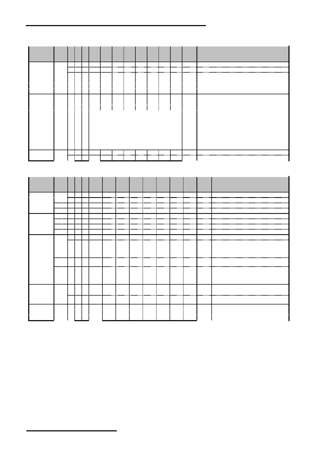
4.4 Commands
4.4.1 EXT select Commands
Para-
Command meter
HEX Descriptions
Ext=0
-
0 1 0
0
0
1
1
0
0
0
0
30 Set Ext=0
Ext=1
-
0 1 0
0
0
1
1
0
0
0
1
31 Set Ext=1
4.4.2 EXT=0 Commands
Para-
Command meter
HEX Descriptions
DISON
-
0 1 0 1
0
1
0
1
1
1
1
AF Display ON
DISOFF
-
0 1 0 1
0
1
0
1
1
1
0
AE Display OFF
DISNOR
-
0 1 0 1
0
1
0
0
1
1
0
A6 Normal Display
DISINV
-
0 1 0 1
0
1
0
0
1
1
1
A7 Inverse Display
COMSCN
-
0 1 0 1
0
1
1
1
0
1
1
BB COM Scan Direction (with 1 parameter)
PB1 1 1 0
*
*
*
*
*
CD2
CD1
CD0
** 000: C0 C79, C80 C159
001: C0 C79, C159 C80
010: C79 C0, C80 C159
011: C79 C0, C159 C80
DISCTRL
-
0 1 0 1
1
0
0
1
0
1
0
CA Display Control (with 3 parameter)
PB1 1 1 0
*
*
*
0
0
CLD
0
0
** CLD=0: CLOCK no division, CD=1: CLOCK divide by 2
PB2 1 1 0
*
*
DT5
DT4
DT3
DT2
DT1
DT0
** DT= (duty no/4 - 1)
PB3 1 1 0
*
*
*
FI
LF3
LF2
LF1
LF0
** FI=inversion type, LF=n-line inversion
SLPIN
-
0 1 0 1
0
0
1
0
1
0
1
95 Sleep In
SLPOUT
-
0 1 0 1
0
0
1
0
1
0
0
94 Sleep Out
LASET
-
0 1 0 0
1
1
1
0
1
0
1
75 Line Address Set (with 2 Parameter)
PB1 1 1 0 SL7 SL6 SL5 SL4 SL3 SL2 SL1 SL0
** Start Line
PB2 1 1 0 EL7 EL6 EL5 EL4 EL3 EL2 EL1 EL0
** End Line
CASET
-
0 1 0 0
0
0
1
0
1
0
1
15 Column Address Set (with 2 Parameter)
PB1 1 1 0 SC7 SC6 SC5 SC4 SC3 SC2 SC1 SC0
** Start Column
PB2 1 1 0 EC7 EC6 EC5 EC4 EC3 EC2 EC1 EC0
** End Column
DATSDR
-
0 1 0 1
0
1
1
1
1
0
0
BC Data Scan Direction (with 3 Parameter)
PB1 1 1 0
*
*
*
*
*
C/L
CI
LI
** Address Scan Direction, C/L=0: column dir; C/L=1: line dir
Column Address Direction, CI=0: normal; CI=1: reverse
Line Address Direction, LI=0: normal; LI=1: inverse
PB2 1 1 0
*
*
*
*
*
*
*
CLR
** Pixel arrangement,
CLR=0: P1, P2, P3….
CLR=1: P3, P2, P1…
PB3 1 1 0
*
*
*
*
*
GS2
GS1
GS0
** GS=001: 32 Gray Scale 2byte 3pixel mode
GS=010: 32 Gray Scale 3byte 3pixel mode
RAMWR
-
0 1 0 0
1
0
1
1
1
0
0
5C Writing to Memory (with data)
Data 1 1 0
Data to be Write
** Data to be Write
:
: : :
:
:
RAMRD
-
0 1 0 0
1
0
1
1
1
0
1
5D Reading from Memory (with data)
Data 1 0 1
Data to be Read
** Data to be Read
:
: : :
:
:
PTLIN
-
0 1 0 1
0
1
0
1
0
0
0
A8 Partial Display In (with 2 parameter)
PB1 1 1 0
*
*
PTS5 PTS4 PTS3 PTS2 PTS1 PTS0
** Start Block Address
PB2 1 1 0
*
*
PTE5 PTE4 PTE3 PTE2 PTE1 PTE0
** End Block Address
PTLOUT
-
0 1 0 1
0
1
0
1
0
0
1
A9 Partial Display Out
RMWIN
-
0 1 0 1
1
1
0
0
0
0
0
E0 Read and Modify Write
RMWOUT
-
0 1 0 1
1
1
0
1
1
1
0
EE Read and Modify Write End
ASCSET
-
0 1 0 1
0
1
0
1
0
1
0
AA Area Scroll Set (with 4 parameter)
PB1 1 1 0
*
*
TB5
TB4
TB3
TB2
TB1
TB0
** Top Block Address
PB2 1 1 0
*
*
BB5
BB4
BB3
BB2
BB1
BB0
** Bottom Block Address
PB3 1 1 0
*
*
NSB5 NSB4 NSB3 NSB2 NSB1 NSB0
** Number of Specified Blocks
PB4 1 1 0
*
*
*
*
*
* SCM1 SCM0
** Area Scroll Mode,
00=Center Mode
01=Top Mode
10=Bottom Mode
11=Whole Mode
SCSTART
-
0 1 0 1
0
1
0
1
0
1
1
AB Scroll Start Set (with 1 parameter)
PB1 1 1 0
*
*
SB5
SB4
SB3
SB2
SB1
SB0
** Start Block Address
OSCON
-
0 1 0 1
1
0
1
0
0
0
1
D1 Internal OSC On
OSCOFF
-
0 1 0 1
1
0
1
0
0
1
0
D2 Internal OSC Off
PWRCTRL
-
0 1 0 0
0
1
0
0
0
0
0
20 Power Control (with 1 parameter)
PB1 1 1 0
*
*
*
0
VB
0
VF
VR
** VR=1: Reference Voltage ON
VF=1: Voltage Follower ON
VB=1: Booster ON
URL: www.topwaydisplay.com
Document Name: LM240160DFW-Manual-Rev0.3
Page: 8 of 11
TOPWAY
LCD Module User Manual
LM240160DFW
4.4.3 EXT=0 Commands (continue)
Para-
Command meter
HEX Descriptions
VOLCTRL
-
0 1 0 1
0
0
0
0
0
0
1
81 EC control (with 2 parameter)
PB1 1 1 0
*
*
VPR5 VPR4 VPR3 VPR2 VPR1 VPR0
** VPR[5:0]
PB2 1 1 0
*
*
*
*
* VPR8 VPR7 BPR6
** VPR[8:6]
VOLUP
-
0 1 0 1
1
0
1
0
1
1
0
D6 EC increase 1
VOLDOWN
-
0 1 0 1
1
0
1
0
1
1
1
D7 EC decrease1
RESERVED
-
0 1 0 1
0
0
0
0
0
1
0
82 Not Use
EPSRRD1
-
0 1 0 0
1
1
1
1
1
0
0
7C Read Register1
EPSRRD2
-
0 1 0 0
1
1
1
1
1
0
1
7D Read Register2
NOP
-
0 1 0 0
0
1
0
0
1
0
1
25 NOP Instruction
STREAD
-
0 0 1
Status
** Status Read
D7=Area Scroll Mode (SCM1)
D6=Area Scroll Mode (SCM0)
D5=1:PMW IN; D5=0:PMW OUT
D4=1:Line Scan Dir; D4=0:Column Scan Dir
D3=1:Display On; D3=0:Display Off
D2=1:EEPROM In Access; D2=0:EEPROM Out Access
D1=1:Display Normal; D1=0:Display Inverse
D0=1:Partial Display On; D0=0:Partial Display Off
EPINT
-
0 1 0 0
0
0
0
0
1
1
1
07 Initial code (with 1 parameter)
PB1 1 1 0 0
0
0
1
1
0
0
1
19
4.4.4 EXT=1 Commands
Para-
Command meter
HEX Descriptions
Gray1 Set
-
0 1 0
0
0
1
0
0
0
0
0
20 Odd Frame Gray PWM Set (with 16 parameter)
PB1 1 1 0
*
*
*
G0F14 G0F13 G0F12 G0F11 G0F10
** Set Gray Level 0 at Odd Frames
:
: : :
*
*
*
:
:
:
:
:
:
:
PB16 1 1 0
*
*
*
G15F14 G15F13 G15F12 G15F11 G15F10
** Set Gray level 15 at Odd Frames
Gray2 Set
-
0 1 0
0
0
1
0
0
0
0
1
21 Even Frame Gray PWM Set (with 16 parameter)
PB1 1 1 0
*
*
*
G0F24 G0F23 G0F22 G0F21 G0F20
** Set Gray Level 0 at Even Frames
:
: : :
*
*
*
:
:
:
:
:
:
:
PB16 1 1 0
*
*
*
G15F24 G15F23 G15F22 G15F21 G15F20
** Set Gray Level 15 at Even Frames
ANASET
-
0 1 0
0
0
1
1
0
0
1
0
32 Analog Circuit Set (with 3 parameter)
PB1 1 1 0
*
*
*
*
*
OSF2
OSF1
OSF0
** OSC Frequency Adjustment
000=12.7kHz, 100=13.2kHz, 010=14.3kHz,
110=15.7kHz, 001=17.3kHz, 101=19.3kHz
011=21.9kHz, 111=25.4kHz
PB2 1 1 0
*
*
*
*
*
*
BE1
BE0
** Booster Efficiency Set
00=3kHz, 01=6kHz, 10=12kHz, 11=24kHz
PB3 1 1 0
*
*
*
*
*
BS2
BS1
BS0
** Bias Set
000=1/14bias, 001=1/13bias, 010=1/12bias,
011=1/11bias, 100=1/10bias, 101=1/9bias,
110=1/7bias, 111=1/5bias
SWINT
-
0 1 0
0
0
1
1
0
1
0
0
34 Software Initial
EPCTIN
-
0 1 0
1
1
0
0
1
1
0
1
CD Control EEPROM (with 1 parameter)
PB1 1 1 0
0
0
EEWR
0
0
0
0
0
** EEW=1, EEPROM Write Enable
EEW=0, EEPROM Read Enable
EPCOUT
-
0 1 0
1
1
0
0
1
1
0
0
CC Cancel EEPROM
EPMWR
-
0 1 0
1
1
1
1
1
1
0
0
FC Write to EEPROM
EPMRD
-
0 1 0
1
1
1
1
1
1
0
1
FD Read from EEPROM
Note: Please refer to ST7529 datasheet for details
4.4.5 Power off the LCD Module
It recommends that enter sleep mode before power off the LCD module.
4.4.6 Refreshing The LCD Module
It recommends that the operating modes and display contents be refreshed periodically to prevent
the effect of unexpected noise.
4.4.7 Using Read EEPROM function for contrast
It recommends to use EPMRD function to ensure the contrast consistencyin batch.
Please refer to ST7529 datasheet for the details of operation.
URL: www.topwaydisplay.com
Document Name: LM240160DFW-Manual-Rev0.3
Page: 9 of 11

TOPWAY
LCD Module User Manual
LM240160DFW
4.5 Basic Operating Sequence (example)
The following setting should be issue to LCD module after hardware reset.
(It is an example only; it could be adjusted if necessary.)
Para-
Command meter
HEX Descriptions
Hard Reset
-
- - -
-
-
-
-
-
-
-
-
-
Hardware Reset by pulling the /RST pin to low
Delay
-
- - -
-
-
-
-
-
-
-
-
-
Wait until Reset Routine to be finish
Ext=0
-
0 1 0 0
0
1
1
0
0
0
0
30 Set Ext=0
SLPOUT
-
0 1 0 1
0
0
1
0
1
0
0
94 Sleep Out
OSCON
-
0 1 0 1
1
0
1
0
0
0
1
D1 Internal OSC On
PWRCTRL
-
0 1 0 0
0
1
0
0
0
0
0
20 Power Control (with 1 parameter)
PB1 1 1 0 0
0
0
0
1
0
0
0
08 Booster ON
Delay
-
- - -
-
-
-
-
-
-
-
-
-
Wait for booster fully on
PWRCTRL
-
0 1 0 0
0
1
0
0
0
0
0
20 Power Control (with 1 parameter)
PB1 1 1 0 0
0
0
0
1
0
1
1
0B Booster ON, Reference Voltage ON, Voltage Follower ON
VOLCTRL
-
0 1 0 1
0
0
0
0
0
0
1
81 EC control (with 2 parameter)
PB1 1 1 0 0
0
1
1
1
1
0
0
3C VPR=033C
PB2 1 1 0 0
0
0
0
0
0
1
1
03
DISCTRL
-
0 1 0 1
1
0
0
1
0
1
0
CA Display Control (with 3 parameter)
PB1 1 1 0 0
0
0
0
0
1
0
0
04 CLD=0: CLOCK no division, CD=1: CLOCK divide by 2
PB2 1 1 0 0
0
1
0
0
1
1
1
27 DT= (duty no/4 - 1)
PB3 1 1 0 0
0
0
0
0
0
0
0
00 FI=0, LF=0
COMSCN
-
0 1 0 1
0
1
1
1
0
1
1
BB COM Scan Direction (with 1 parameter)
PB1 1 1 0 0
0
0
0
0
0
0
1
01 001: C0 C79, C159 C80
DATSDR
-
0 1 0 1
0
1
1
1
1
0
0
BC Data Scan Direction (with 3 Parameter)
PB1 1 1 0 0
0
0
0
0
0
0
1
01 C/L=0, Address Scan Direction by column
CI=0, Column Address Direction is normal
LI=1, Line Address Direction is inverse
PB2 1 1 0 0
0
0
0
0
0
0
0
00 CLR=0: Pixel arrangement are P1, P2, P3….
PB3 1 1 0 0
0
0
0
0
0
1
0
02 GS=010: 32 Gray Scale 3byte 3pixel mode
Ext=1
-
0 1 0 0
0
1
1
0
0
0
1
31 Set Ext=1
ANASET
-
0 1 0 0
0
1
1
0
0
1
0
32 Analog Circuit Set (with 3 parameter)
PB1 1 1 0 0
0
0
0
0
1
0
1
05 OSF=101, OSC Frequency Adjustment101=19.3kHz
PB2 1 1 0 0
0
0
0
0
0
0
0
00 BE=00, Booster Efficiency Set 3kHz
PB3 1 1 0 0
0
0
0
0
0
1
0
02 BS=010, Bias Set 1/12bias
Ext=0
-
0 1 0 0
0
1
1
0
0
0
0
30 Set Ext=0
INITIAL
-
0 1 0 0
0
0
0
0
1
1
1
07 Generate ACK
CODE1
PB1 1 1 0 0
0
0
1
1
0
0
1
19 Read for use ACK funtion
Ext=1
-
0 1 0 0
0
1
1
0
0
0
1
31 Set Ext=1
CONTROL
-
0 1 0 1
1
0
0
1
1
0
1
CD
EEPROM
PB1 1 1 0 0
0
0
0
0
0
0
0
00 Enable EEPROM
delay 100ms
READ
-
0 1 0 1
1
1
1
1
1
0
1
FD Read data from EEPROM
EEPROM
delay 100ms
CANEL
-
0 1 0 1
1
0
0
1
1
0
0
CC Canel operation EEPROM
EEPROM
Ext=0
-
0 1 0 0
0
1
1
0
0
0
0
30 Set Ext=0
DISON
-
0 1 0 1
0
1
0
1
1
1
1
AF Display ON
CASET
-
0 1 0 0
0
0
1
0
1
0
1
15 Column Address Set (with 2 Parameter)
PB1 1 1 0 0
0
0
0
0
0
0
0
00 Start at 00
PB2 1 1 0 0
1
0
0
1
1
1
1
4F End at (240/3)-1=79
LASET
-
0 1 0 0
1
1
1
0
1
0
1
75 Line Address Set (with 2 Parameter)
PB1 1 1 0 0
0
0
0
0
0
0
0
00 Start at 00
PB2 1 1 0 1
0
0
1
1
1
1
1
9F End at 160-1=159
RAMWR
-
0 1 0 0
1
0
1
1
1
0
0
5C Writing to Memory (with data)
Data 1 1 0
Data to be Write
** Display Data to be Write
:
: : :
:
:
:
Note: Please refer to ST7529 datasheet for details
URL: www.topwaydisplay.com
Document Name: LM240160DFW-Manual-Rev0.3
Page: 10 of 11

TOPWAY
LCD Module User Manual
LM240160DFW
Design and Handling Precaution
Please refer to "LCD-Module-Design-Handling-Precaution.pdf".
URL: www.topwaydisplay.com
Document Name: LM240160DFW-Manual-Rev0.3
Page: 11 of 11