LM240160PCW
LCD Module User Manual
Prepared by:
Checked by:
Approved by:
Wangxikuan
Date: 2019-05-14
Date:
Date:
Rev. Descriptions
Release Date
0.1
Preliminary release
2019-05-14
URL: www.topwaydisplay.com
Document Name: LM240160PCW-Manual-Rev0.1
Page: 1 of 16

TOPWAY
LCD Module User Manual
LM240160PCW
Table of Content
1. Basic Specifications .............................................................................................................. 3
1.1
Display Specifications ............................................................................................................................................ 3
1.2
Mechanical Specifications ...................................................................................................................................... 3
1.3
Block Diagram ........................................................................................................................................................ 3
1.4
Terminal Functions ................................................................................................................................................. 4
2. Absolute Maximum Ratings .................................................................................................. 5
3. Electrical Characteristics ...................................................................................................... 5
3.1
DC Characteristics ................................................................................................................................................. 5
3.2
LED Backlight Circuit Characteristics ..................................................................................................................... 5
3.3
AC Characteristics ................................................................................................................................................. 6
3.4
Reset Timing .......................................................................................................................................................... 9
4. Function Specifications ...................................................................................................... 10
4.1
Resetting the LCD module ................................................................................................................................... 10
4.2
Display Memory Map ........................................................................................................................................... 10
4.3
Commands ........................................................................................................................................................... 11
4.4
Command Table ................................................................................................................................................... 14
URL: www.topwaydisplay.com
Document Name: LM240160PCW-Manual-Rev0.1
Page: 2 of 16
TOPWAY
LCD Module User Manual
LM240160PCW
1. Basic Specifications
1.1 Display Specifications
1) LCD Display Mode
: FSTN, Positive, Transmissve
2) Display Color
: Display Data = “1” : Dark Gray (*1)
: Display Data = “0” : Light Gray (*2)
3) Viewing Angle
: 12H
4) Driving Method
: 1/160 duty, 1/12 bias
5) Back Light
: White LED backlight
Note:
*1. Color tone may slightly change by Temperature and Driving Condition.
*2. The Color is defined as the inactive / background color
*3. Fine Contrast adjustment function is necessary in the application design for optimal display result
1.2 Mechanical Specifications
1) Outline Dimension
: 70.0 x 47.9 x 10.0 MAX
(See attached Outline Drawing for details)
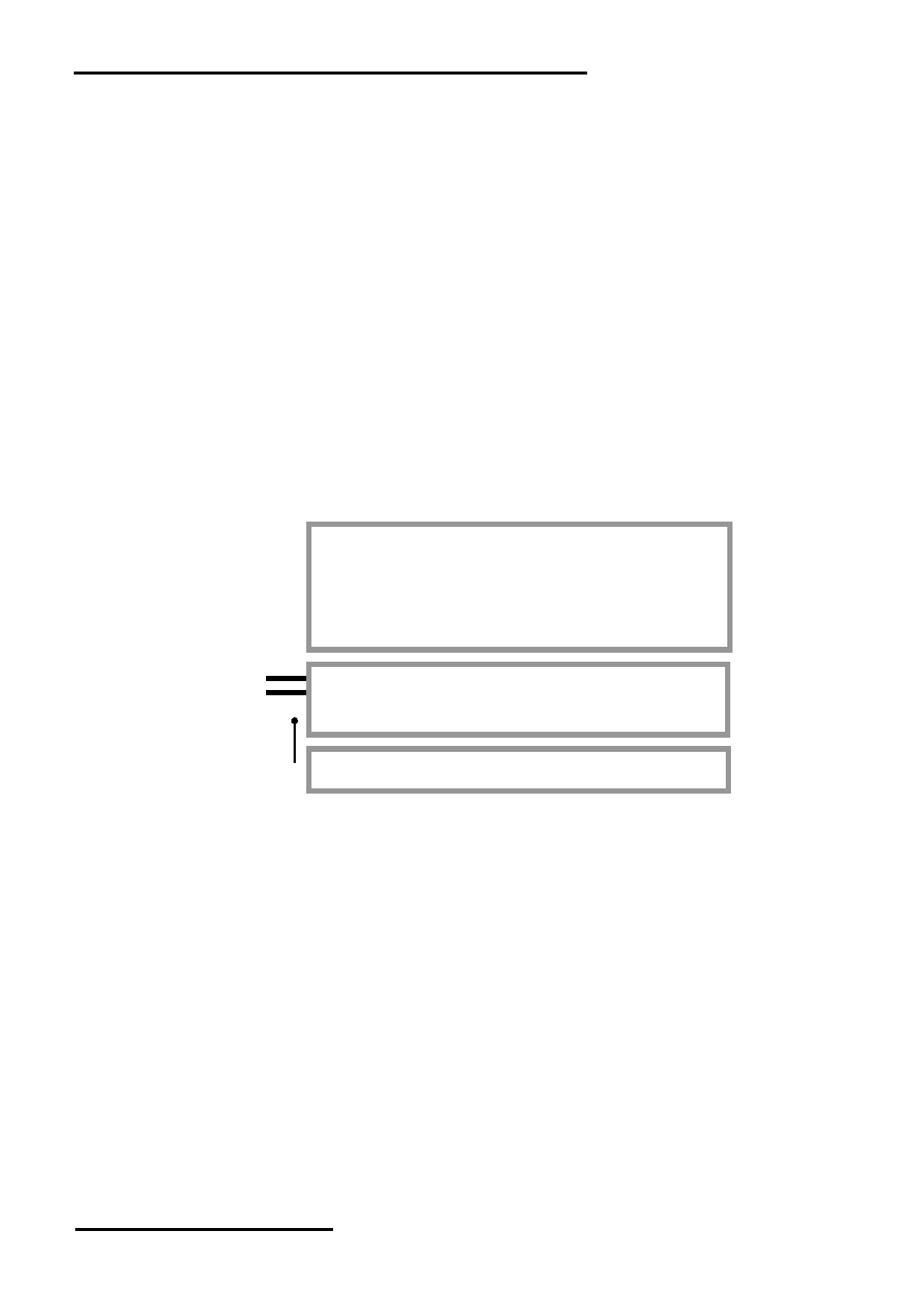
1.3 Block Diagram
LCD Panel
240 x 160 pixels
DB0 ~ DB7
UC1611S
/CS, /RST, D/C, /WR, /RD
VDD
or
VSS
equivalent
Back Light Circuit
BLA
URL: www.topwaydisplay.com
Document Name: LM240160PCW-Manual-Rev0.1
Page: 3 of 16
TOPWAY
LCD Module User Manual
LM240160PCW
1.4 Terminal Functions
Pin No.
Descriptions
(K1/K2)
Pin Name
I/O
8-bit parallel
8-bit parallel
8080 mode
6800 mode
Serial mode
1
VSS
Power 0V Supply, Ground (0V)
2
VDD
Power Positive Power Supply
3
DB7
I/O
8-bit Data bus;
Not use
:
:
Three state I/O terminal for display data or
7
DB3(SDA)
instruction data
Serial data input(DB3)
when /CS =H,
:
:
DB0~DB7=High Impedance
Not use
10
DB0(SCL)
Serial clock input(DB0)
11
/RD(E)
Input /WR=H, /RD=L;
R/W=H,E=H;
Not used,
12
/WR(R/W)
Input Data or Status read
Data or Status read Connect to VSS
form the LCD module
from the LCD module
/WR=L H, /RD=H;
R/W=L,E=H L;
Data or Instruction
Data or Status latch
latch into the LCD
into the LCD module
module
13
D/C
Input Register Select
D/C=HIGH: data on DB0 to DB7 is display data
D/C=LOW: data on DB0 to DB7 is control data
14
/RST
Input Reset:
/RST=LOW: Initialization is executed
/RST=HIGH: Normal
15
/CS
Input Chip Select
/CS=LOW : Data IO is enabled
16
BLA
Power Backlight Positive Power Supply
Interface setting:
Setting
8080 mode
6800 mode
SPI/4-wire mode
JP1
OPEN
OPEN
OPEN
JP2
CLOSE
CLOSE
CLOSE
JP3
OPEN
OPEN
CLOSE
JP4
CLOSE
CLOSE
OPEN
JP5
OPEN
CLOSE
OPEN
JP6
CLOSE
OPEN
CLOSE
JP7,JP8
OPEN
OPEN
CLOSE
JP9,JP10
OPEN
OPEN
OPEN
Note:
*1. Default Setting: 8080 mode.
URL: www.topwaydisplay.com
Document Name: LM240160PCW-Manual-Rev0.1
Page: 4 of 16
TOPWAY
LCD Module User Manual
LM240160PCW
2. Absolute Maximum Ratings
Items
Symbol
Min.
Max.
Unit Condition
Supply Voltage
V DD
-0.3
+4.0
V
V SS = 0V
Input Voltage
V IN
-0.3
V DD +0.3
V
V SS = 0V
Operating Temperature
T OP
-20
+70
C
No Condensation
Storage Temperature
T ST
-30
+80
C
No Condensation
Cautions:
Any Stresses exceeding the Absolute Maximum Ratings may cause substantial damage to the device. Functional
operation of this device at other conditions beyond those listed in the specification is not implied and prolonged exposure
to extreme conditions may affect device reliability.
3. Electrical Characteristics
3.1 DC Characteristics
V SS =0V, V DD =3.3V, T OP =25 C
Items
Symbol
MIN.
TYP
MAX.
Unit Condition /
.
Application Pin
Operating Voltage
V DD
3.0
3.3
3.6
V
VDD
Input High Voltage
V IH
0.8xV DD
-
V DD
V
/RST, /CS, D/C, /WR, /RD,
Input Low Voltage
V IL
0
-
0.2xV DD
V
DB0~DB7
Operating Current
I DD
-
1.0
3.8
mA VDD
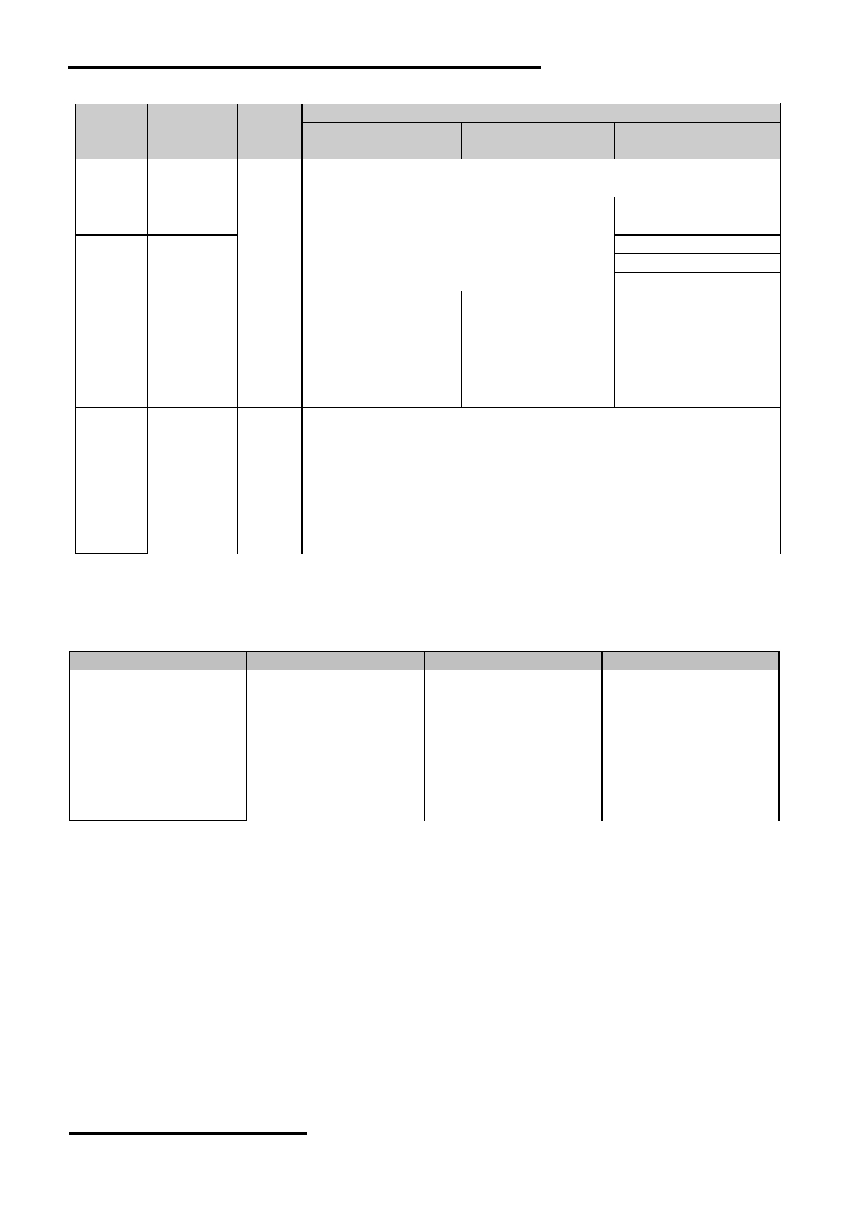
3.2 LED Backlight Circuit Characteristics
V SS =0V, If BLA =43mA, T OP =25 C
Items
Symbol
MIN.
TYP.
MAX.
Unit Applicable Pin
Forward Voltage
Vf BLA
-
3.3
-
V
BLA
Forward Current
If BLA
-
51
60
mA BLA
Cautions:
Exceeding the recommended driving current could cause substantial damage to the backlight and shorten its lifetime.
BLA
VSS
No. of LED = 3pcs
URL: www.topwaydisplay.com
Document Name: LM240160PCW-Manual-Rev0.1
Page: 5 of 16
TOPWAY
LCD Module User Manual
LM240160PCW
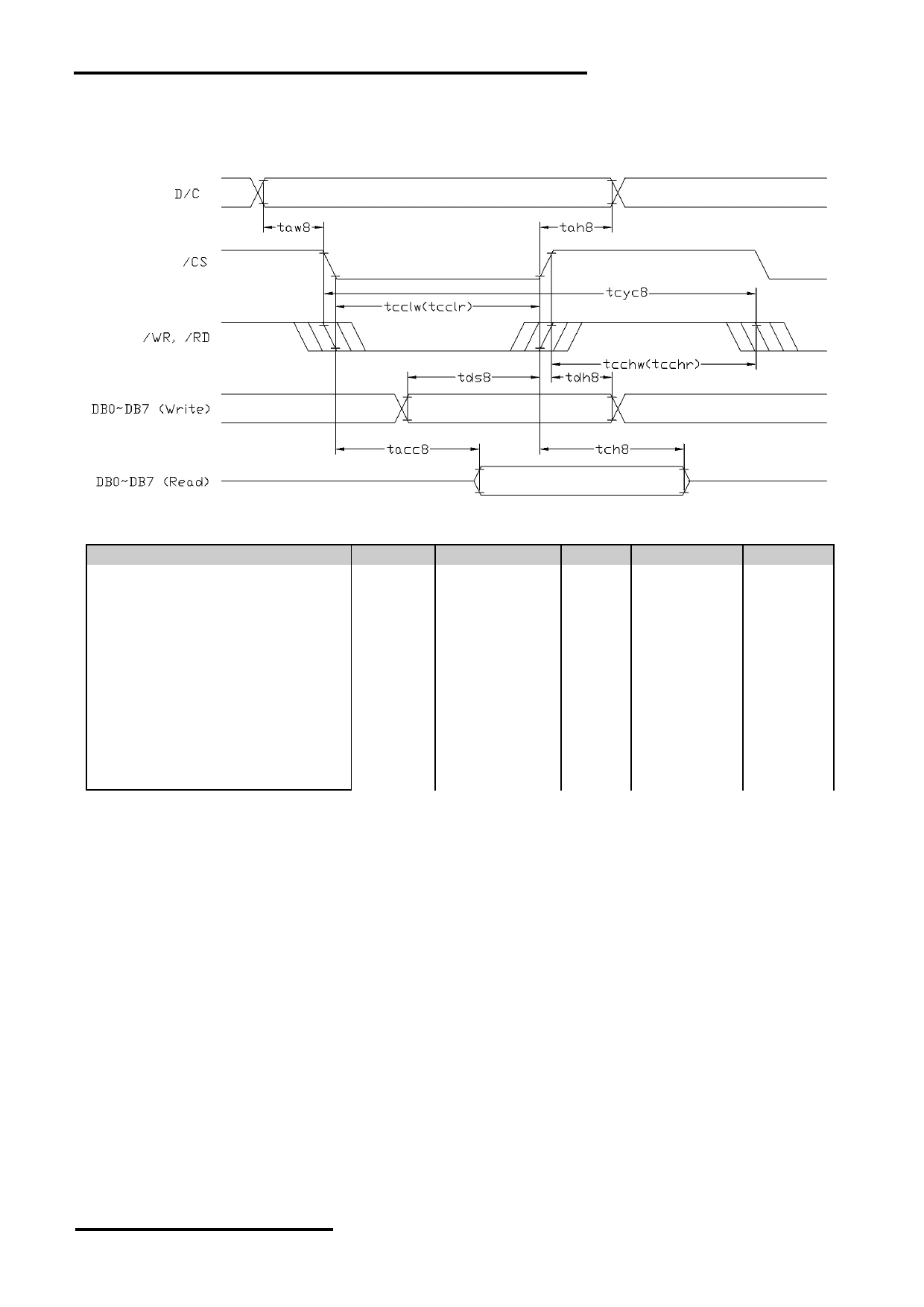
3.3 AC Characteristics
3.3.1 8080 Mode System Bus Timing
V SS =0V, V DD =3.3V, T OP =25 C
Item
Symbol
MIN.
TYP.
MAX.
Unit
System cycle time
tcyc8
185
-
-
ns
Address setup time (D/C)
taw8
10
-
-
ns
Address hold time (D/C)
tah8
10
-
-
ns
Control LOW pulse width (/WR)
tcclw
93
-
-
ns
Control LOW pulse width (/RD)
tcclr
93
-
-
ns
Control HIGH pulse width (/WR)
tcchw
93
-
-
ns
Control HIGH pulse width (/RD)
tcchr
93
-
-
ns
Data setup time
tds8
43
-
-
ns
Data hold time
tdh8
10
-
-
ns
/RD access time (*2)
tacc8
-
-
85
ns
Output disable time (*2)
tch8
21
-
-
ns
Note:
*1. Input signal rise/fall time should be less than 12ns
*2. CL=100pF
URL: www.topwaydisplay.com
Document Name: LM240160PCW-Manual-Rev0.1
Page: 6 of 16
TOPWAY
LCD Module User Manual
LM240160PCW
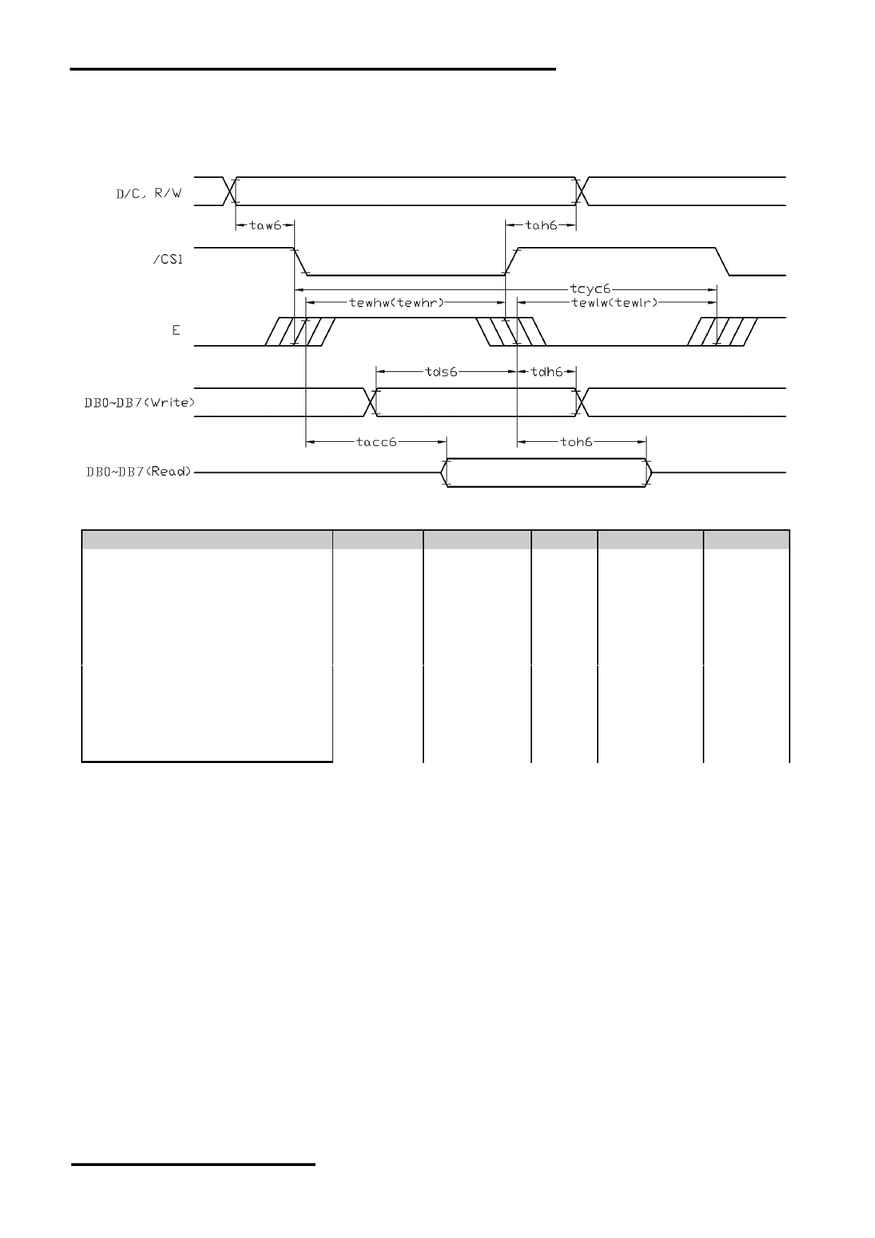
3.3.2 6800 Mode System Bus Timing
V SS =0V, V DD =3.3V, T OP =25 C
Item
Symbol
MIN.
TYP.
MAX.
Unit
System cycle time
tcyc6
185
-
-
ns
Address setup time (D/C)
taw6
10
-
-
ns
Address hold time (D/C)
tah6
10
-
-
ns
Control LOW pulse width (R/W)
tewlr
93
-
-
ns
Control LOW pulse width (R/W)
tewlw
93
-
-
ns
Control HIGH pulse width (/RD)
tewhr
93
-
-
ns
Control HIGH pulse width (R/W)
tewhw
93
-
-
ns
Data setup time
tds6
43
-
-
ns
Data hold time
tdh6
10
-
-
ns
/RD access time (*2)
tacc6
-
-
85
ns
Output disable time (*2)
toh6
21
-
-
ns
Note:
*1. Input signal rise/fall time should be less than 12ns
*2. CL=100pF
URL: www.topwaydisplay.com
Document Name: LM240160PCW-Manual-Rev0.1
Page: 7 of 16
TOPWAY
LCD Module User Manual
LM240160PCW
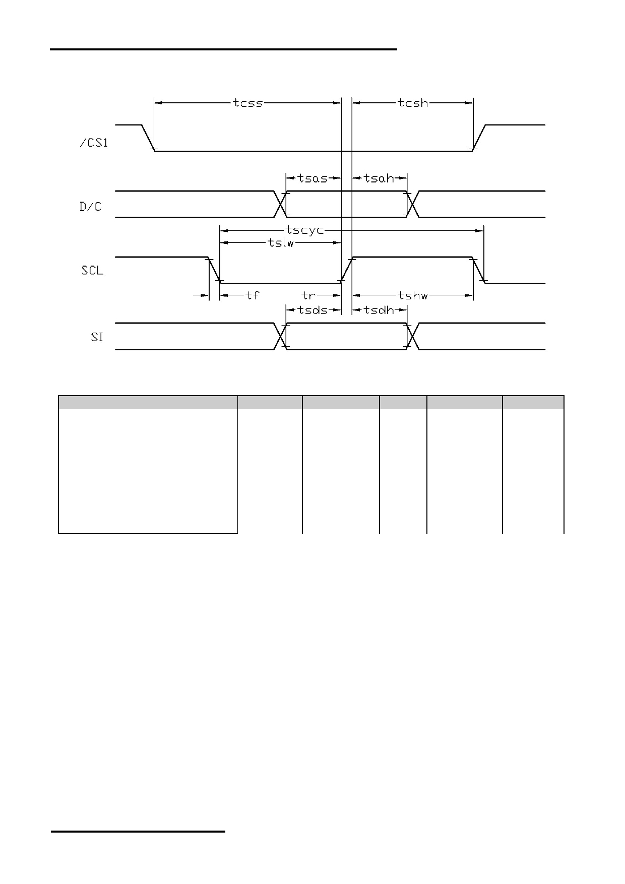
3.3.3 Serial Mode Interface
V SS =0V, V DD =3.3V, T OP =25 C
Item
Symbol
MIN.
TYP.
MAX.
Unit
Serial Clock Period
tscyc
51
-
-
ns
Address setup time (D/C)
tsas
10
-
-
ns
Address hold time (D/C)
tsah
10
-
-
ns
SCL “H” pulse width
tshw
26
-
-
ns
SCL “L” pulse width
tslw
26
-
-
ns
Data setup time
tsds
21
-
-
ns
Data hold time
tsdh
10
-
-
ns
CS-SCL time
tcss
10
-
-
ns
CS-SCL time
tcsh
10
-
-
ns
Note:
*1. Input signal rise/fall time should be less than 12ns
URL: www.topwaydisplay.com
Document Name: LM240160PCW-Manual-Rev0.1
Page: 8 of 16
TOPWAY
LCD Module User Manual
LM240160PCW
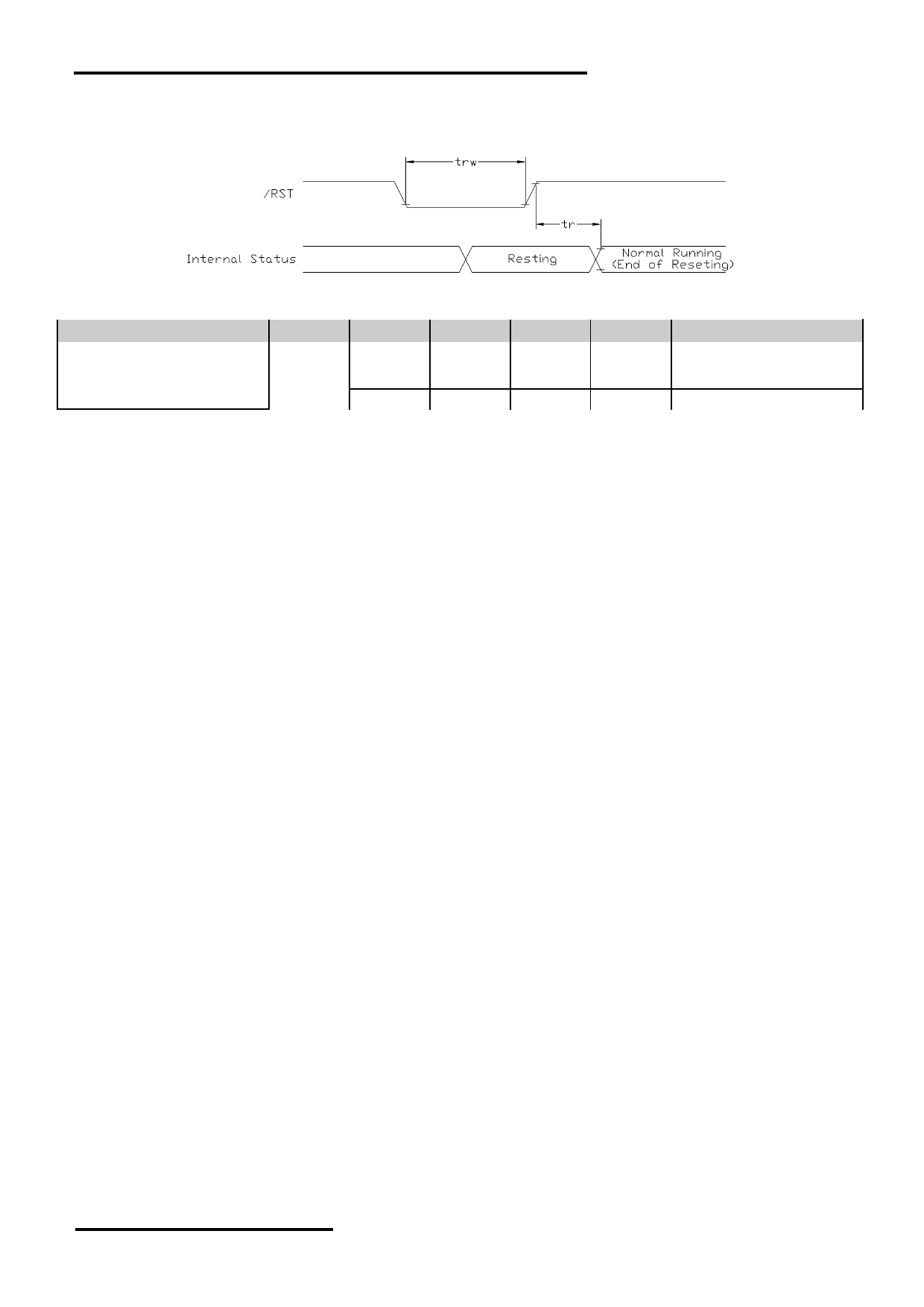
3.4 Reset Timing
V SS =0V, V DD =3.3V, T OP =25 C
Item
Symbol
MIN.
TYP.
MAX.
Unit
Note
Reset LOW pulse width
trw
4
-
-
μs
-
-
Reset time
tr
-
-
15
ms
-
-
200
ms
Using MTP Function
Note:
*1. Input signal rise/fall time should be less than 12ns
*2. Please refer to UC1611 data sheet for details
URL: www.topwaydisplay.com
Document Name: LM240160PCW-Manual-Rev0.1
Page: 9 of 16
TOPWAY
LCD Module User Manual
LM240160PCW
4. Function Specifications
4.1 Resetting the LCD module
The LCD module should be initialized by using /RST terminal.
While turning on the VDD and VSS power supply, maintain /RST terminal at LOW level. After the
power supply stabilized, release the reset terminal (/RST=HIGH)
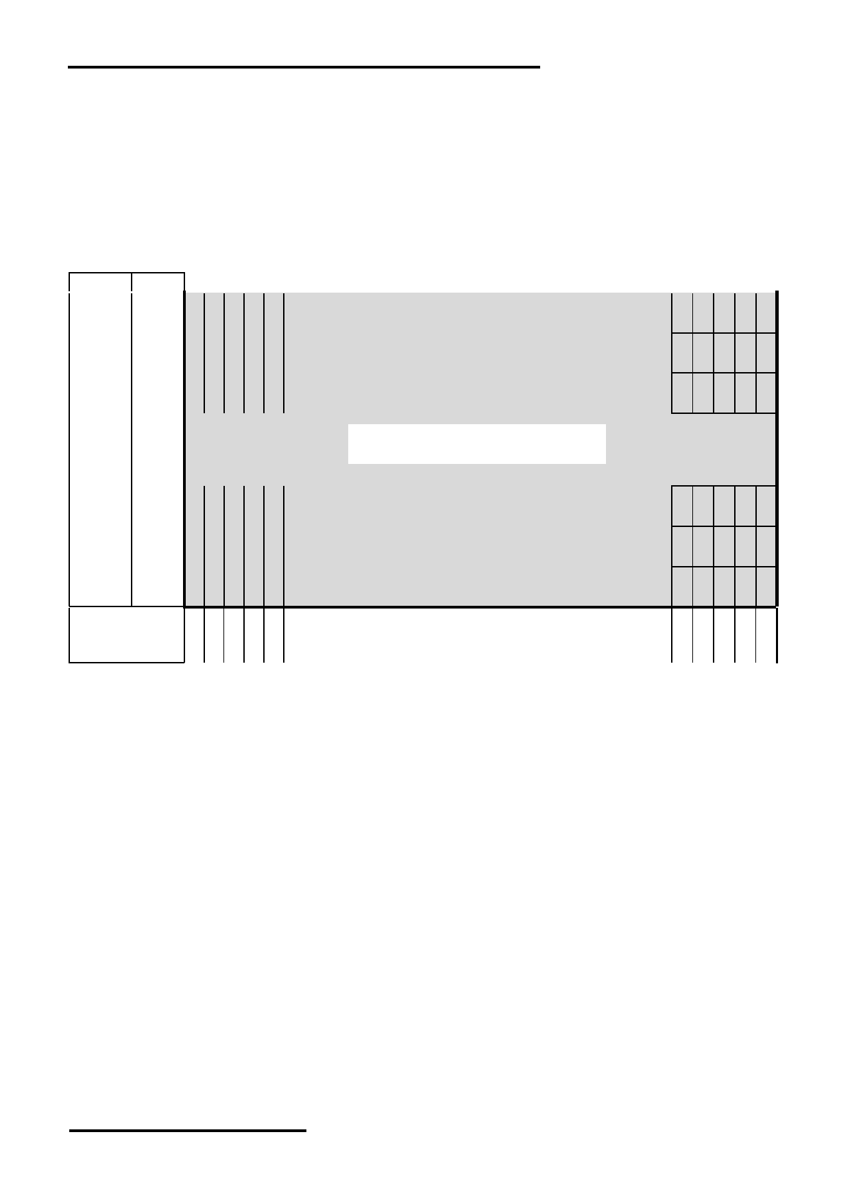
4.2 Display Memory Map
Page
data
LCD Display (front view)
D0
0
:
D7
D0
1
:
D7
D0
2
:
D7
:
:
:
240x160 Pixels
:
D0
17
:
D7
D0
18
:
D7
D0
19
:
D7
Column
Address
……
(dec)
Pixel mapping (Top View)
Note:
* 1. Based on the top view of the LCD module,
*2. The above is memory map based on:
On/Off mode setting, DC[5:3]=100 (1bpp) ,the Page value range: 0 ~ 19
LC[0]=MSF=0
LC[1]=MX=1
LC[2]=MY=0
SL=0
*3. For 4,8 and 16 Gray-shade operation please refer to UC1611 datasheet.
URL: www.topwaydisplay.com
Document Name: LM240160PCW-Manual-Rev0.1
Page: 10 of 16
TOPWAY
LCD Module User Manual
LM240160PCW
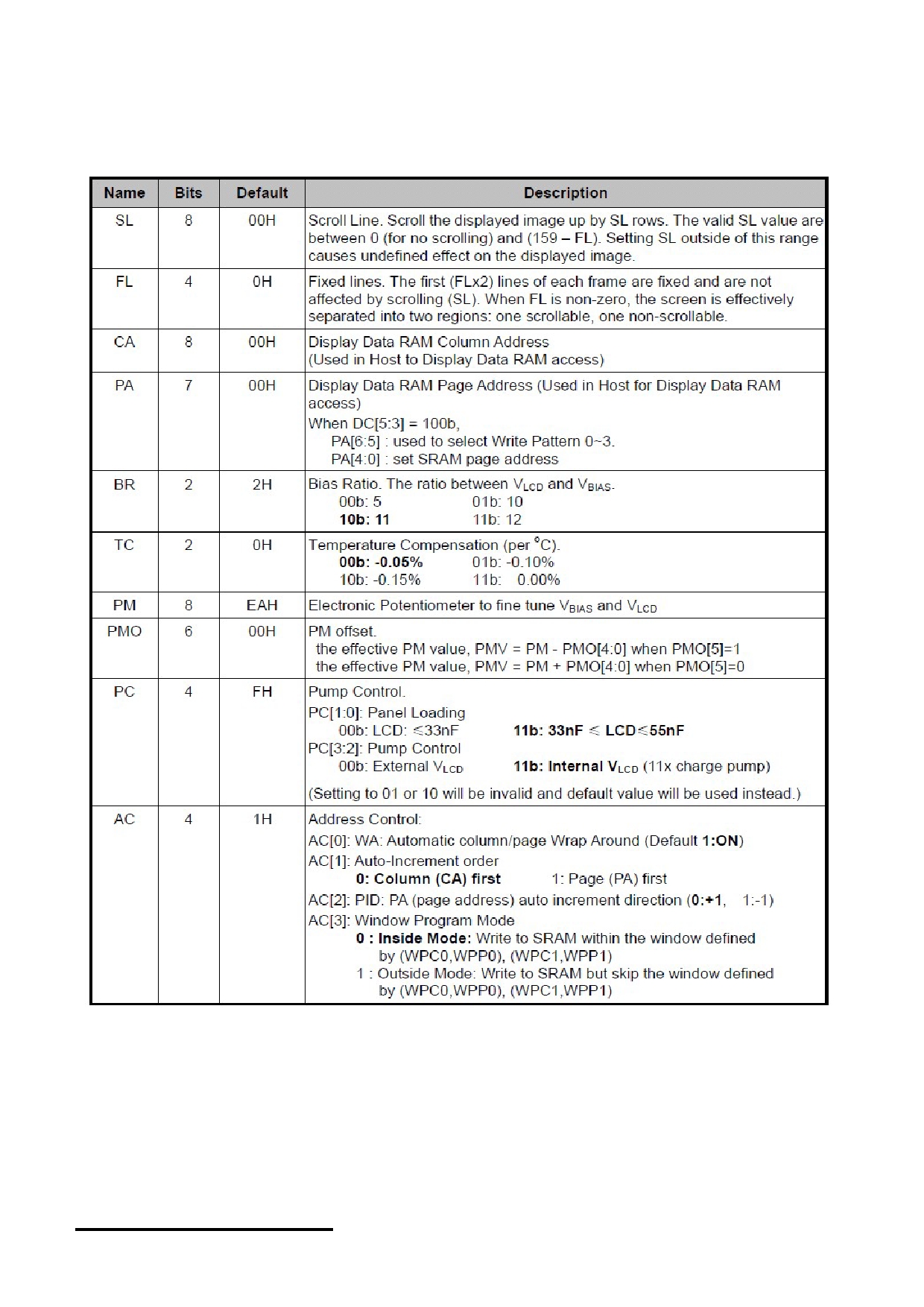
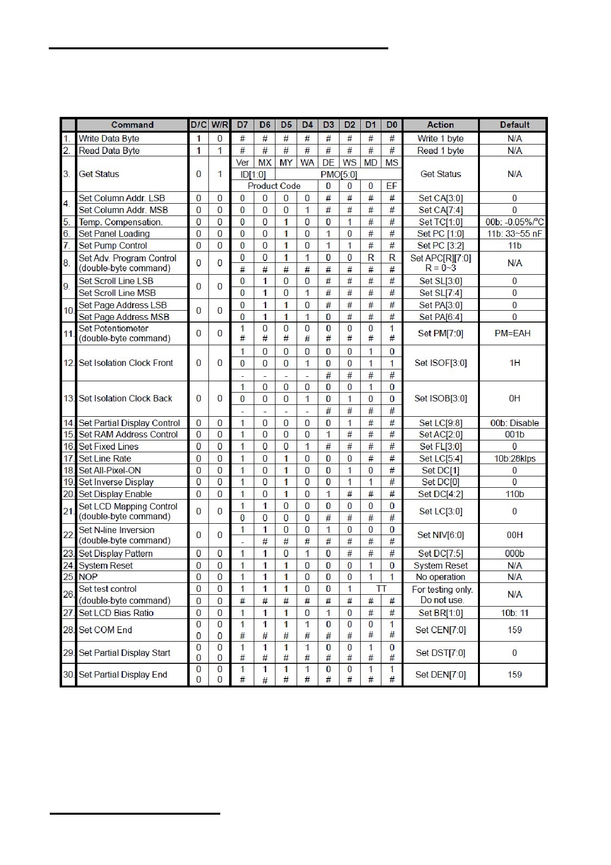
4.3 Commands
4.3.1 Register Table
URL: www.topwaydisplay.com
Document Name: LM240160PCW-Manual-Rev0.1
Page: 11 of 16
TOPWAY
LCD Module User Manual
LM240160PCW
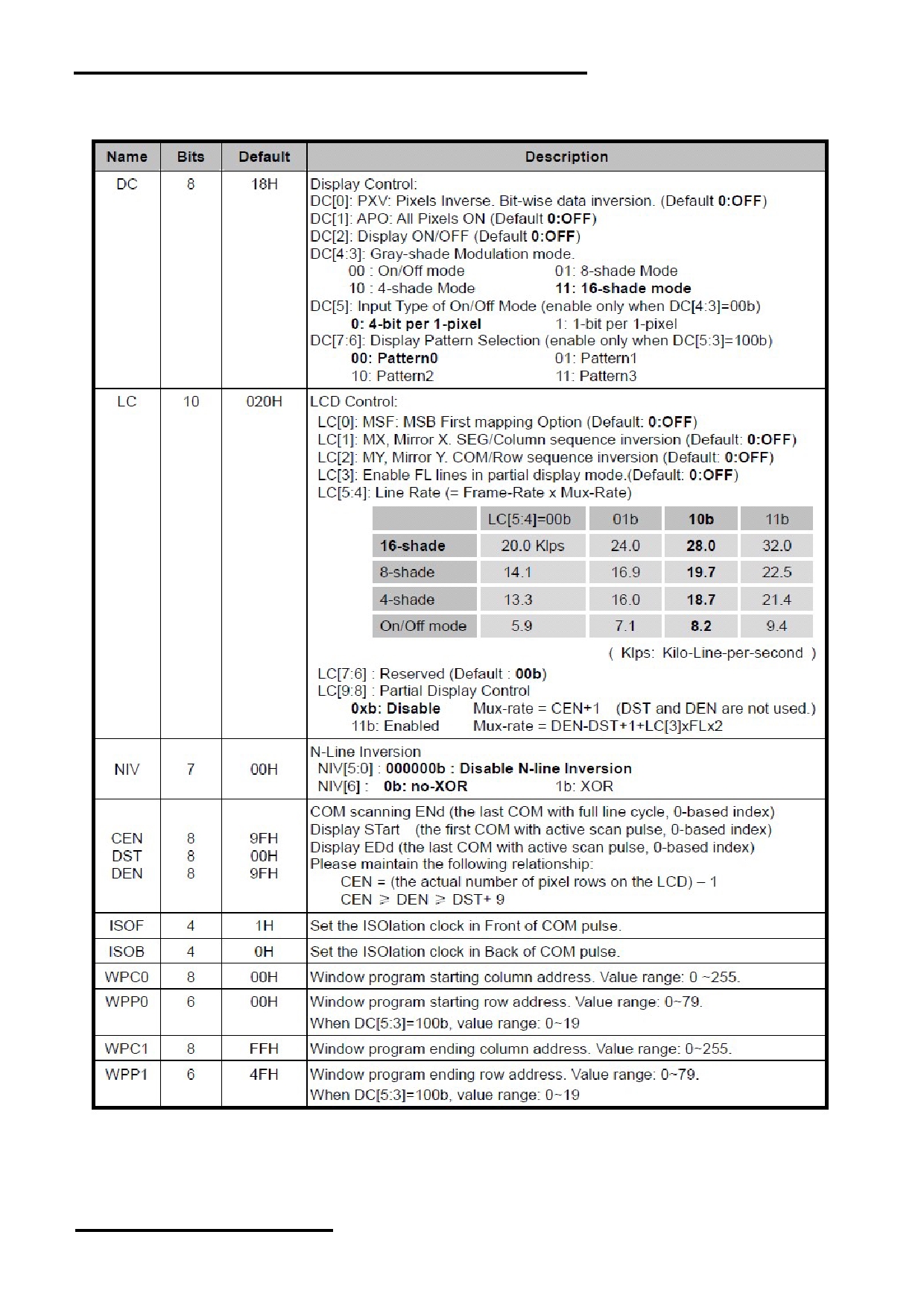
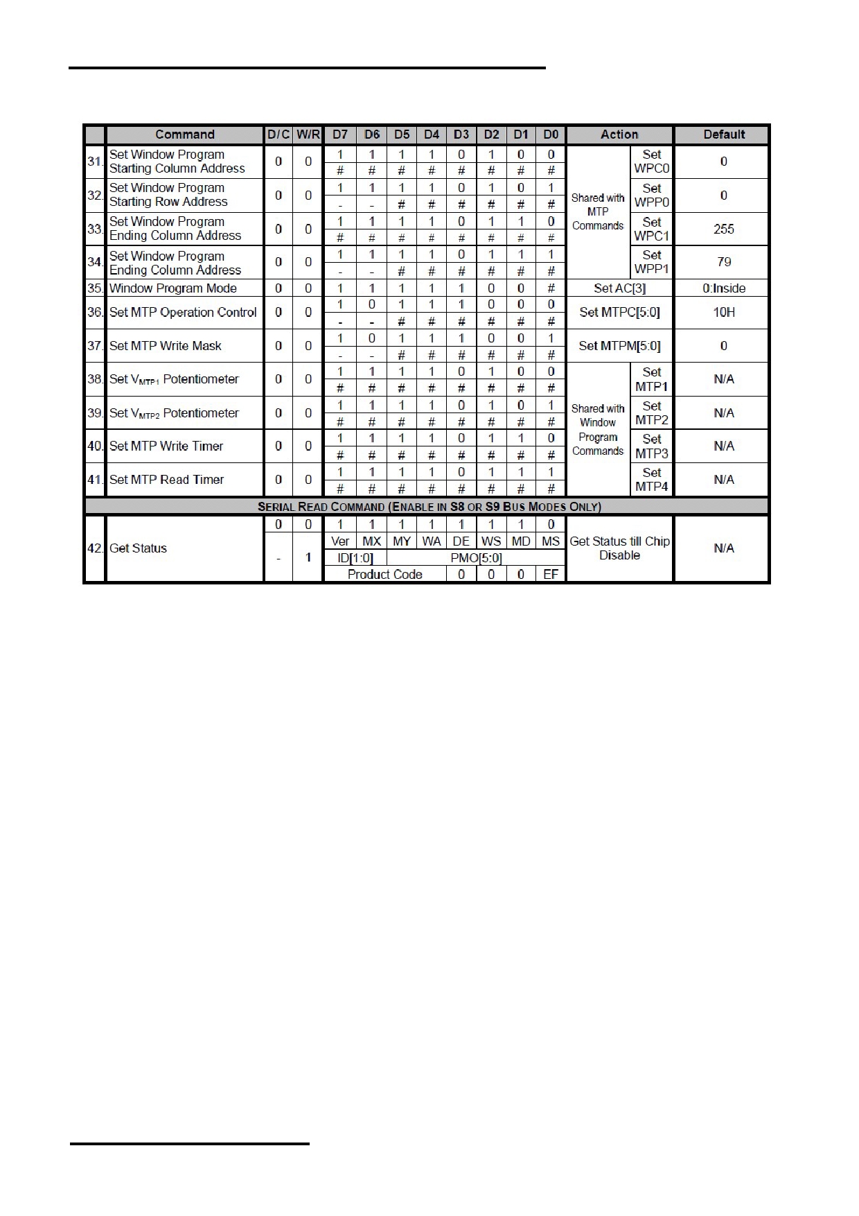
Register Table (continue)
URL: www.topwaydisplay.com
Document Name: LM240160PCW-Manual-Rev0.1
Page: 12 of 16
TOPWAY
LCD Module User Manual
LM240160PCW
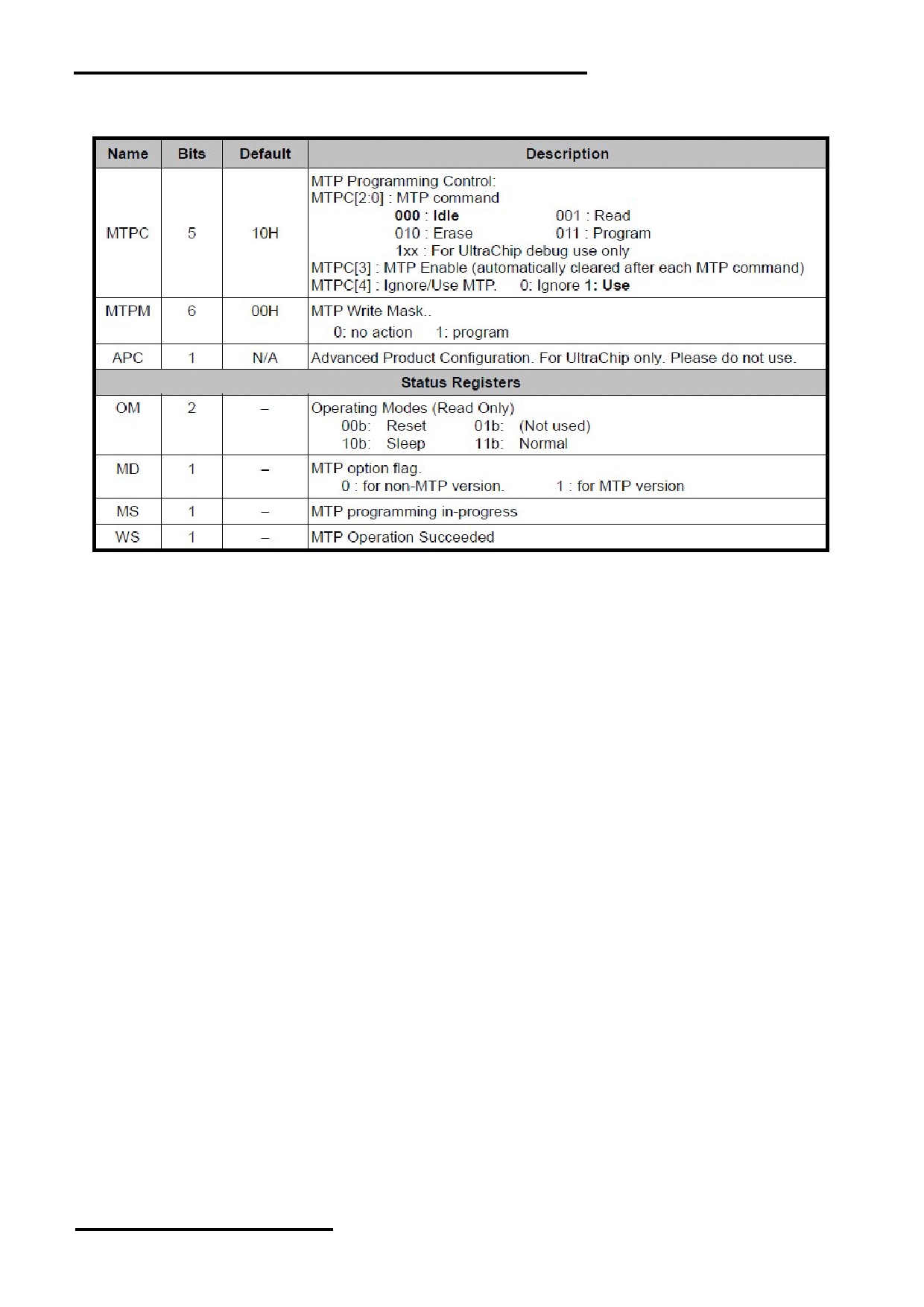
Register Table (continue)
URL: www.topwaydisplay.com
Document Name: LM240160PCW-Manual-Rev0.1
Page: 13 of 16
TOPWAY
LCD Module User Manual
LM240160PCW
4.4 Command Table
The following setting should be issue to LCD module after hardware reset.
(It is an example only; it could be adjusted if necessary.)
URL: www.topwaydisplay.com
Document Name: LM240160PCW-Manual-Rev0.1
Page: 14 of 16
TOPWAY
LCD Module User Manual
LM240160PCW
Command Table (continue)
Note:
Please refer to UC1611 data sheet for details
R/W=0 means it is a write function, R/W=1 means it is a read function
D/C=0 means it is a control data, D/C=1 means it is a display data
URL: www.topwaydisplay.com
Document Name: LM240160PCW-Manual-Rev0.1
Page: 15 of 16

TOPWAY
LCD Module User Manual
LM240160PCW
Design and Handling Precaution
Please refer to "LCD-Module-Design-Handling-Precaution.pdf".
URL: www.topwaydisplay.com
Document Name: LM240160PCW-Manual-Rev0.1
Page: 16 of 16