
Model No.LMT150DNGFWD-1
MODEL NO. : LMT150DNGFWD-1
ISSUED DATE : 2017-06-07
VERSION
: V2.0
■ Preliminary Specification
□ Final Product Specification
Customer :
Approved by
Notes
TOPWAY Confirmed :
Prepared by
Checked by
Approved by
Liu Tihou
This technical specification is subjected to change without notice
The information contained herein is the exclusive property of SHENZHEN TOPWAY TECHNOLOGY CO.,LTD
and shall not be distributed, reproduced, or disclosed in whole or in part without prior written permission of
SHENZHEN TOPWAY TECHNOLOGY CO.,LTD.
Page 1 of 18

Model No.LMT150DNGFWD-1
Table of Contents
Table of Contents ............................................................................................................................ 2
Record of Revision.......................................................................................................................... 3
1 General Specifications.............................................................................................................. 4
2 Input/Output Terminals ............................................................................................................. 5
3 Absolute Maximum Ratings...................................................................................................... 7
4 Electrical Characteristics .......................................................................................................... 8
5 Dispaly Colors And Input Data Information ............................................................................. 10
6 Timing Chart........................................................................................................................... 12
7 Optical Characteristics.............................................................................................................. 14
8 Environmental / Reliability Test................................................................................................. 17
9 Precautions for Use of LCD Modules........................................................................................18
The information contained herein is the exclusive property of SHENZHEN TOPWAY TECHNOLOGY CO.,LTD
and shall not be distributed, reproduced, or disclosed in whole or in part without prior written permission of
SHENZHEN TOPWAY TECHNOLOGY CO.,LTD.
Page 2 of 18

Model No.LMT150DNGFWD-1
Record of Revision
Rev
Issued Date
Description
Editor
1.0
2016-05-04
Preliminary Product Specification Released.
Chen Ji
2.0
2017-06-07 Update Section 2.2
Liu Tihou
The information contained herein is the exclusive property of SHENZHEN TOPWAY TECHNOLOGY CO.,LTD
and shall not be distributed, reproduced, or disclosed in whole or in part without prior written permission of
SHENZHEN TOPWAY TECHNOLOGY CO.,LTD.
Page 3 of 18
Model No.LMT150DNGFWD-1
1 General Specifications
Feature
Spec
Size
15 inch
Resolution
1024xRGBx768
Technology Type
a-Si
Display Spec.
Pixel Configuration
RGB vertical stripe
Pixel pitch(mm)
0.297(H) × 0.297(V)
Display Mode
TM with Normally White
Surface Treatment
Anti Glare
Viewing Direction
12:00
Gray Scale Inversion Direction
6:00
LCM (W x H x D) (mm)
326.5(H)×253.5 (V) ×11.8 (D) (typ.)
Active Area(mm)
304.128(W) x 228.096 (V) (typ.)
Mechanical
With /Without TSP
Without TSP
Connection Type
Socket
Characteristics
Weight (g)
TBD
LED backlight type
Backlight
Replaceable lamp holder for
backlight
Electrical
Interface
LVDS 1 port
Characteristics
Color Depth
16.2M/262K
Note 1: Viewing direction for best image quality is different from TFT definition. There is a 180 degree
shift.
Note 2: Requirements on Environmental Protection: RoHS
Note 3: LCM weight tolerance: ± 5%
The information contained herein is the exclusive property of SHENZHEN TOPWAY TECHNOLOGY CO.,LTD
and shall not be distributed, reproduced, or disclosed in whole or in part without prior written permission of
SHENZHEN TOPWAY TECHNOLOGY CO.,LTD.
Page 4 of 18

Model No.LMT150DNGFWD-1
2 Input/Output Terminals
2.1 LCD PINS
CN1 socket(Module side): 185083-20121 ( P-TWO ELECTRIC TECHNOLOGY CO., LTD.)
Pin No.
Symbol
Signal
Input data signal: 8bit
Input data signal:6bit
Remarks
1
VCC
Power supply
Power supply
2
VCC
3
GND
Ground
Ground
4
REV
Selection of
High: Reverse scan
scan direction
Low or Open: Normal scan
5
D0-
Pixel data
R0-R5,G0
6
D0+
7
GND
Ground
Ground
8
D1-
Pixel data
G1-G5,B0-B1
9
D1+
10
GND
Ground
Ground
11
D2-
Pixel data
B2-B5,DE
12
D2+
13
GND
Ground
Ground
14
CLK-
Pixel clock
Pixel clock
15
CLK+
16
GND
Ground
Ground
17
D3-
R6-R7,
Pixel data
G6-G7,
Ground
18
D3+
B6-B7
19
NC
Non
-
connection
Selection of
20
SEL6/8
the number of
Low
High or Open
colors
The information contained herein is the exclusive property of SHENZHEN TOPWAY TECHNOLOGY CO.,LTD
and shall not be distributed, reproduced, or disclosed in whole or in part without prior written permission of
SHENZHEN TOPWAY TECHNOLOGY CO.,LTD.
Page 5 of 18

Model No.LMT150DNGFWD-1
2.2 BACKLIGHT PINS
CN2: MSB24038P5 (Produced by STM) or equivalent.
Pin
Symbol
Description
5
VDD
12V
4
GND
Ground
Back light ON/OFF control:
3
BRTC
5V-On / 0V-Off
2
PWM
PWM Luminance control(Active high)
PWM= Hi,100% Drive
PWM= Lo,0% Drive
1
NC
NC
2.3 POSITIONS OF PLUG AND SOCKET
The information contained herein is the exclusive property of SHENZHEN TOPWAY TECHNOLOGY CO.,LTD
and shall not be distributed, reproduced, or disclosed in whole or in part without prior written permission of
SHENZHEN TOPWAY TECHNOLOGY CO.,LTD.
Page 6 of 18

Model No.LMT150DNGFWD-1
3 Absolute Maximum Ratings
AGND=GND=0V, Ta = 25 ℃
Parameter
Symbol
Rating
Unit
Remarks
Power Supply Voltage
VCC
-0.3~+3.96
V
Ta = 25°C
Input voltage for signals
Vi
-0.5~+3.96
V
Ta = 25°C
Storage temperature
Tst
-30 ~ +80
°C
Note 1
Operating temperature
Top
-20 ~ +70
°C
Note 1, 2
3
Absolute humidity
AH
≤ 70
g/m
Ta > 50°C
Note1: Temperature and relative humidity range is shown in the figure below.
(a) 90%RH Max. (Ta≤ 40°C)
(b) Wet-bulb temperature should be39°C Max. (Ta> 40°C)
(c) No condensation.
Note2: The temperature of panel display surface area should be -20°C Min and 70°C Max.
The information contained herein is the exclusive property of SHENZHEN TOPWAY TECHNOLOGY CO.,LTD
and shall not be distributed, reproduced, or disclosed in whole or in part without prior written permission of
SHENZHEN TOPWAY TECHNOLOGY CO.,LTD.
Page 7 of 18

Model No.LMT150DNGFWD-1
4 Electrical Characteristics
4.1 Driving For LCD
AGND=GND=0V, Ta = 25 ℃
Parameter
Symbol
min.
typ.
max.
Uni
Remarks
t
Power supply voltage
VCC
3.0
3.3
3.6
V
-
Power supply ripple
Vp-p
200
mV
Including
spike noise
Power supply current
ICC
-
550
-
mA
Note 1
Permissible ripple voltage
VRP
-
-
100
mV
Differential input voltage
︱ Vid ︱
250
450
mV
Differential input
High
VTH
-
-
100
mV
VCM = 1.25V
threshold voltage for
Low
VTL
-100
-
mV
LVDS receiver
Note2
Input voltage width for LVDS
Vi
0
-
1.90
V
-
receiver
Terminating resistor
RT
-
100
-
Ω
-
Rush current
I rush
-
-
1.5
A
Note3
Input voltage for
High
VFH
0.7VCC
VCC
V
MSL signals
Low
VFL
0
0.3VCC
V
Note 1: Black mode, 65MHz, at VCC = 3.3V.
Note 2: Common mode voltage for LVDS receiver.
Note 3: Measurement Conditions:
(Ta=25°C) Note1
4.2 Driving For Backlight
Parameter
Symbol
min.
typ.
max.
Unit
Remarks
Power supply voltage
VDD
10.8
12.0
12.6
V
Power supply current
IDD
-
TBD
-
mA
Light bar life time
Hr
30000
50000
-
Hour
Note1
Input voltage for
High
VDFH1
2.0
5.0
V
PWM signal
Low
VDFL1
0
0.4
V
Input voltage for
High
VDFH2
2.0
5.0
V
BRTC signal
Low
VDFL2
0
0.4
V
PWM frequency
fpwm
200
(20K)
Hz
PWM pulse width
tPWH
10
us
Note1: Optical performance should be evaluated at Ta=25 ℃ .Only If LED is driven by high
current, high ambient temperature & humidity condition. The life time of LED will be
reduced. Operating life means brightness goes down to 50% of initial brightness.
Typical operating life time is an estimated data.
The information contained herein is the exclusive property of SHENZHEN TOPWAY TECHNOLOGY CO.,LTD
and shall not be distributed, reproduced, or disclosed in whole or in part without prior written permission of
SHENZHEN TOPWAY TECHNOLOGY CO.,LTD.
Page 8 of 18
Model No.LMT150DNGFWD-1
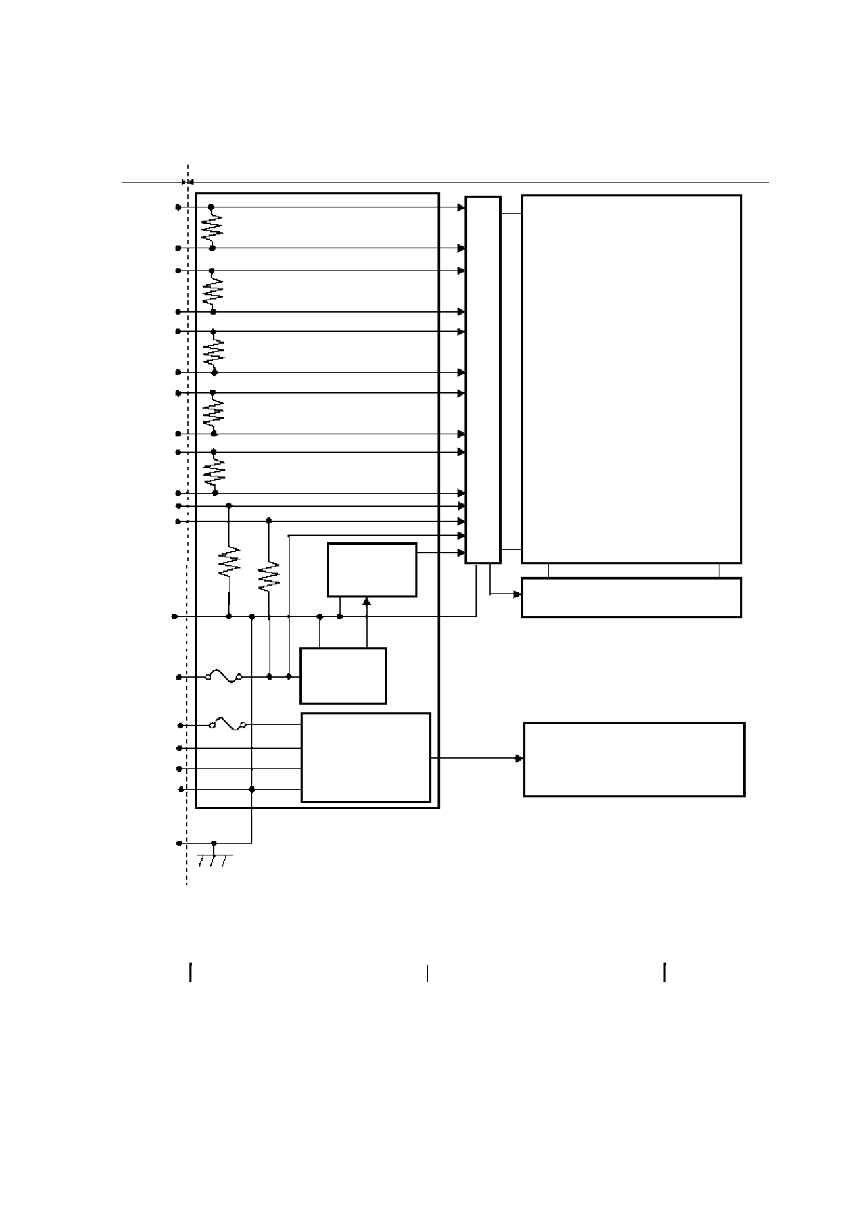
4.3 Block Diagram
Host
LCD module Product)
D0+
100
D0-
LCD panel
D1+
100
D1-
H: 1024 × 3 (R, G, B)
V: 768
D2+
100
D2-
D3+
100
D3-
CLK+
100
CLK-
DPS
FRC
768 lines
Power supply
for gradation
V-driver
GND
Note1
Note2
Fuse
DC/DC
VCC
converter
Fuse
VDD
PWM
LED driver
BRTC
LED Backlight
GND
LCD panel signal processing board
FG
Note1: Relations between GND (Signal ground and LED driver ground) and FG (Frame ground)
in the LCD module are as follows:
GND - FG
Connected
Note2: GND and FG must be connected to customer equipment’s ground, and it is
recommended that these grounds be connected together in customer equipment.
The information contained herein is the exclusive property of SHENZHEN TOPWAY TECHNOLOGY CO.,LTD
and shall not be distributed, reproduced, or disclosed in whole or in part without prior written permission of
SHENZHEN TOPWAY TECHNOLOGY CO.,LTD.
Page 9 of 18

Model No.LMT150DNGFWD-1
5 DISPLAY COLORS AND INPUT DATA INFORMATION
5.1 DISPLAY COLORS AND DATA SIGNAL
This product can display in equivalent to 16,194,277 colors in 253 scales. Also the relation
between display colors and input data signals is as the following table. And it can display in
equivalent to 262,144 colors in 64 scales, without data signals R7, R6, G7, G6, B7, B6 in the
following table.
Display
Data signal ( 0:Low level , 1:High Level )
colors
R7 R6 R5 R4 R3 R2 R1 R0
G7 G6 G5 G4 G3 G2 G1 G0
B7 B6 B5 B4 B3 B2 B1 B0
Black
0 0 0 0 0 0 0 0
0 0 0 0 0 0 0 0
0 0 0 0 0 0 0 0
Blue
0 0 0 0 0 0 0 0
0 0 0 0 0 0 0 0
1 1 1 1 1 1 1 1
Red
1 1 1 1 1 1 1 1
0 0 0 0 0 0 0 0
0 0 0 0 0 0 0 0
Magenta
1 1 1 1 1 1 1 1
0 0 0 0 0 0 0 0
1 1 1 1 1 1 1 1
Green
0 0 0 0 0 0 0 0
1 1 1 1 1 1 1 1
0 0 0 0 0 0 0 0
Cyan
0 0 0 0 0 0 0 0
1 1 1 1 1 1 1 1
1 1 1 1 1 1 1 1
Yellow
1 1 1 1 1 1 1 1
1 1 1 1 1 1 1 1
0 0 0 0 0 0 0 0
White
1 1 1 1 1 1 1 1
1 1 1 1 1 1 1 1
1 1 1 1 1 1 1 1
Black
0 0 0 0 0 0 0 0
0 0 0 0 0 0 0 0
0 0 0 0 0 0 0 0
Dark
0 0 0 0 0 0 0 1
0 0 0 0 0 0 0 0
0 0 0 0 0 0 0 0
0 0 0 0 0 0 1 0
0 0 0 0 0 0 0 0
0 0 0 0 0 0 0 0
:
:
:
Bright
1 1 1 1 1 1 0 1
0 0 0 0 0 0 0 0
0 0 0 0 0 0 0 0
Red
1 1 1 1 1 1 1 0
0 0 0 0 0 0 0 0
0 0 0 0 0 0 0 0
1 1 1 1 1 1 1 1
0 0 0 0 0 0 0 0
0 0 0 0 0 0 0 0
Black
0 0 0 0 0 0 0 0
0 0 0 0 0 0 0 0
0 0 0 0 0 0 0 0
Dark
0 0 0 0 0 0 0 0
0 0 0 0 0 0 0 1
0 0 0 0 0 0 0 0
0 0 0 0 0 0 0 0
0 0 0 0 0 0 1 0
0 0 0 0 0 0 0 0
:
:
:
Bright
0 0 0 0 0 0 0 0
1 1 1 1 1 1 0 1
0 0 0 0 0 0 0 0
Green
0 0 0 0 0 0 0 0
1 1 1 1 1 1 1 0
0 0 0 0 0 0 0 0
0 0 0 0 0 0 0 0
1 1 1 1 1 1 1 1
0 0 0 0 0 0 0 0
Black
0 0 0 0 0 0 0 0
0 0 0 0 0 0 0 0
0 0 0 0 0 0 0 0
Dark
0 0 0 0 0 0 0 0
0 0 0 0 0 0 0 0
0 0 0 0 0 0 0 1
0 0 0 0 0 0 0 0
0 0 0 0 0 0 0 0
0 0 0 0 0 0 1 0
:
:
:
Bright
0 0 0 0 0 0 0 0
0 0 0 0 0 0 0 0
1 1 1 1 1 1 0 1
Blue
0 0 0 0 0 0 0 0
0 0 0 0 0 0 0 0
1 1 1 1 1 1 1 0
0 0 0 0 0 0 0 0
0 0 0 0 0 0 0 0
1 1 1 1 1 1 1 1
The information contained herein is the exclusive property of SHENZHEN TOPWAY TECHNOLOGY CO.,LTD
and shall not be distributed, reproduced, or disclosed in whole or in part without prior written permission of
SHENZHEN TOPWAY TECHNOLOGY CO.,LTD.
Page 10 of 18

Model No.LMT150DNGFWD-1
5.2 DATA MAP
(1) LVDS Input data signal: 8bit
(2) LVDS Input data signal: 6bit
The information contained herein is the exclusive property of SHENZHEN TOPWAY TECHNOLOGY CO.,LTD
and shall not be distributed, reproduced, or disclosed in whole or in part without prior written permission of
SHENZHEN TOPWAY TECHNOLOGY CO.,LTD.
Page 11 of 18

Model No.LMT150DNGFWD-1
6 Timing Chart
6.1 TIMING CHARACTERISTICS
Parameter
Symbol
min.
typ.
max.
Unit
Remarks
1/tc
52
56.88
71
MHz
Clock
Frequency
17.58ns
tc
19.23
17.58
14.08
ns
(typ.)
Horizontal
Cycle
th
1114
1200
1400
CLK
signals
Display period
thd
1024
-
Vertical
Cycle
tv
778
790
845
H
60.0Hz(typ.)
signals
Display period
tvd
768
-
6.2 INPUT SIGNAL TIMING CHART
Horizontal timing
tc
CLK
DATA
(R0-R7) (R0-R5)
INVALID
1
2
1023 1024
INVALID
(G0-G7) or (G0-G5)
(B0-B7) (B0-B5)
DE
thd
th
Vertical timing
DATA
(R0-R7) (R0-R5)
INVALID
INVALID
(G0-G7) or (G0-G5)
(B0-B7) (B0-B5)
1 2
767 768
DE
tvd
tv
The information contained herein is the exclusive property of SHENZHEN TOPWAY TECHNOLOGY CO.,LTD
and shall not be distributed, reproduced, or disclosed in whole or in part without prior written permission of
SHENZHEN TOPWAY TECHNOLOGY CO.,LTD.
Page 12 of 18
Model No.LMT150DNGFWD-1
6.3 PIXEL DATA ALIGNMENT OF DISPLAY IMAGE
The following chart is the coordinates of per pixel
D(1,1)
D(2,1)
D(3,1)
D(1024,1)
D(1,1)
D(1,2)
D(2,2)
D(3,2)
D(1024,2)
B
G
R
D(1,3)
D(2,3)
D(3,3)
D(1024,3)
D(1,768)
D(2,768)
D(3,768)
D(1024,768)
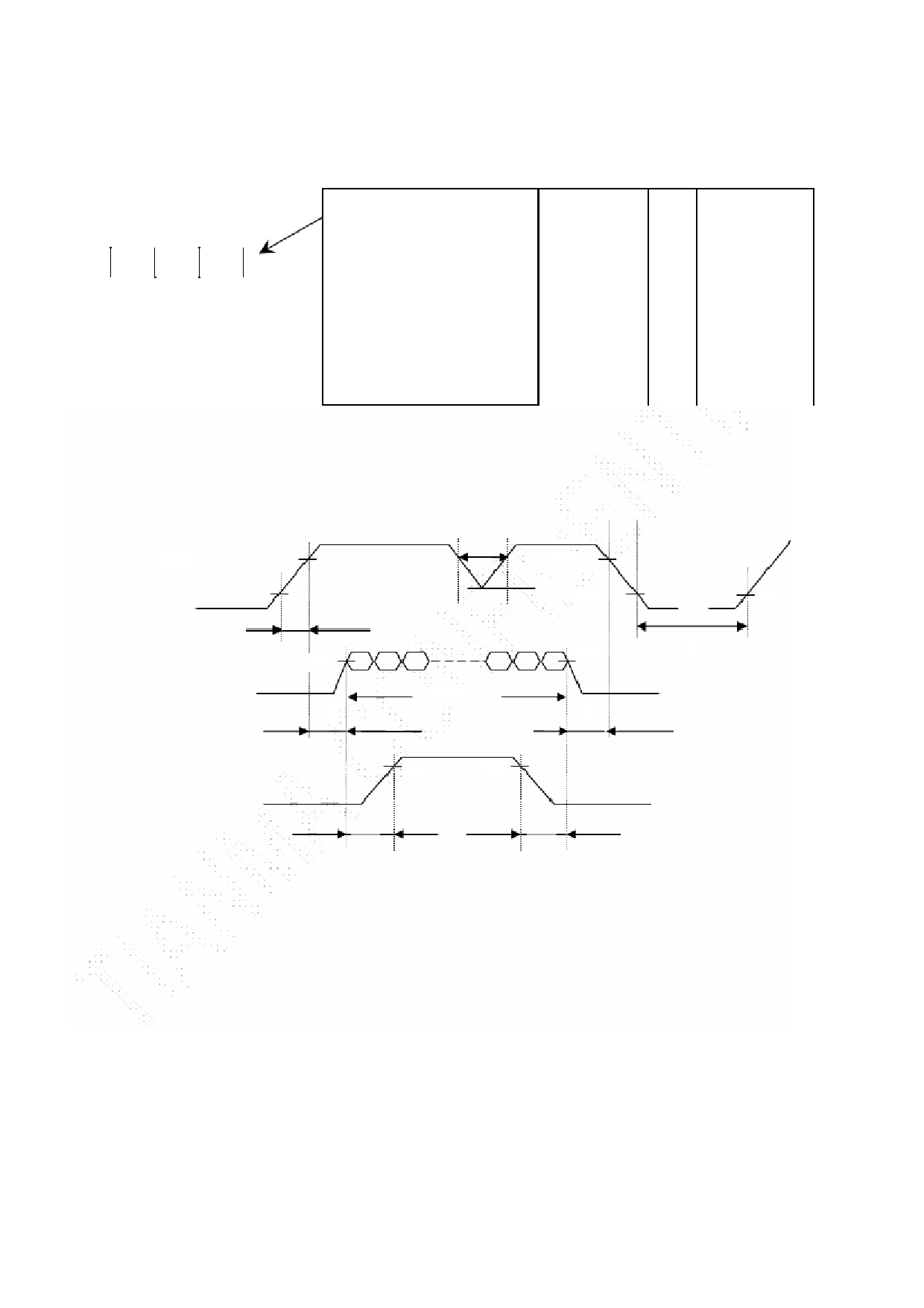
6.4 POWER SUPPLY VOLTAGE SEQUENCE
6.4.1 The sequence of backlight and power
ON
t < 10ms *1
90%
VCC
3.0 V 90%
10%
2.5 V
0V
10%
10%
t1
90%
t4
90%
Display Signals
0V
VALID
t2
t3
90%
90%
Backlight signal
t5
t6
Timing Specifications:
t1 :0.5ms<t1 <10ms;
t2 :0.5 ms<t2 <50ms;
t3 :0ms<t3 <50ms;
t4 :t4 >1000ms;
t5 :t5 >200ms;
t6 :t6 >200ms;
The information contained herein is the exclusive property of SHENZHEN TOPWAY TECHNOLOGY CO.,LTD
and shall not be distributed, reproduced, or disclosed in whole or in part without prior written permission of
SHENZHEN TOPWAY TECHNOLOGY CO.,LTD.
Page 13 of 18

Model No.LMT150DNGFWD-1
7 Optical Characteristics
Item
Symbol Condition
Min
Typ.
Max
Unit
Remark
θ T
70
80
-
View Angles
θ B
CR ≧ 10
70
80
-
Degree Note 2
θ L
70
80
-
θ R
70
80
-
Contrast Ratio
CR
θ= 0 °
600
800
-
-
Note1
Note3
Luminance uniformity
U
-
1.25
1.33
-
Note6
Response Time
T ON
25 ℃
-
8
12
ms
Note1
T OFF
Note4
x
0.263
0.313
0.363
White
y
0.279
0.329
0.379
x
0.582
0.632
0.682
Red
Note5
Chromaticity
Backlight is
y
0.305
0.355
0.405
-
Note1
x
on
0.294
0.344
0.394
Green
y
0.558
0.608
0.658
x
0.107
0.157
0.207
Blue
y
0.037
0.087
0.137
NTSC
50
60
-
%
Note5
Luminance
L
400
450
-
cd/ ㎡ Note7
Test Conditions:
1. The ambient temperature is 25 ℃ . VDD= 3.3V, VCC=12V, 100% brightness,
2. The test systems refer to Note 1 and Note2.
The information contained herein is the exclusive property of SHENZHEN TOPWAY TECHNOLOGY CO.,LTD
and shall not be distributed, reproduced, or disclosed in whole or in part without prior written permission of
SHENZHEN TOPWAY TECHNOLOGY CO.,LTD.
Page 14 of 18

Model No.LMT150DNGFWD-1
Note 1: Definition of optical measurement system.
The optical characteristics should be measured in dark room. After 5 Minutes operation, the optical
properties are measured at the center point of the LCD screen. All input terminals LCD panel must
be ground when measuring the center area of the panel.
Item
Photo detector Field
Photo detector
Contrast Ratio
Field
Luminance
SR-3A
1°
Chromaticity
500mm
Lum Uniformity
TFT-LCD Module
LCD Panel
Response Time
BM-7A
2°
The center of the screen
Note 2: Definition of viewing angle range and measurement system.
viewing angle is measured at the center point of the LCD by CONOSCOPE(ergo-80) 。
Note 3: Definition of contrast ratio
“White state “: The state is that the LCD should drive by Vwhite.
“Black state”: The state is that the LCD should drive by Vblack.
Vwhite: To be determined Vblack: To be determined.
The information contained herein is the exclusive property of SHENZHEN TOPWAY TECHNOLOGY CO.,LTD
and shall not be distributed, reproduced, or disclosed in whole or in part without prior written permission of
SHENZHEN TOPWAY TECHNOLOGY CO.,LTD.
Page 15 of 18

Model No.LMT150DNGFWD-1
Note 4: Definition of Response time
The response time is defined as the LCD optical switching time interval between “White” state and
“Black” state. Rise time (T ON ) is the time between photo detector output intensity changed from 90%
to 10%. And fall time (T OFF ) is the time between photo detector output intensity changed from 10%
to 90%.
Note 5: Definition of color chromaticity (CIE1931)
Color coordinates measured at center point of LCD.
Note 6: Definition of Luminance Uniformity
Active area is divided into 9 measuring areas (Refer Fig. 2). Every measuring point is placed at the
center of each measuring area.
Luminance Uniformity (U) = Lmin/ Lmax
L-------Active area length W----- Active area width
Lmax: The measured Maximum luminance of all measurement position.
Lmin: The measured Minimum luminance of all measurement position.
Note 7: Definition of Luminance:
Measure the luminance of white state at center point.
The information contained herein is the exclusive property of SHENZHEN TOPWAY TECHNOLOGY CO.,LTD
and shall not be distributed, reproduced, or disclosed in whole or in part without prior written permission of
SHENZHEN TOPWAY TECHNOLOGY CO.,LTD.
Page 16 of 18

Model No.LMT150DNGFWD-1
8 Environmental / Reliability Test
No
Test Item
Condition
Remarks
1
High Temperature
Ts = +70 ℃ , 240 hours (Note1)
IEC60068-2-1:2007
Operation
GB2423.2-2008
2
Low Temperature
Ta = -20 ℃ , 240 hours (Note1)
IEC60068-2-1:2007
Operation
GB2423.1-2008
3
High Temperature
Ta = +80 ℃ , 240 hours
IEC60068-2-1:2007
Storage
GB2423.2-2008
4
Low Temperature
Ta = -30 ℃ , 240 hours
IEC60068-2-1:2007
Storage
GB2423.1-2008
Storage at High
5
IEC60068-2-78 :2001
Temperature and
Ta = +50 ℃ , 80% RH max, 240hours
Humidity
GB/T2423.3—2006
Start with cold temperature,
6
Thermal Shock
-20 ℃ 30 min ~ +60 ℃ 30 min,
End with high temperature,
(non-operation)
Change time:5min, 20 Cycle
IEC60068-2-14:1984,
GB2423.22-2002
C=150pF, R=330 Ω, 5point/panel
Air: ±15Kv, 9points,25times/point;
7 ESD(Operation)
IEC61000-4-2:2001
Contact: ±8Kv, 9points,25times/point
(Environment: 15 ℃ ~35 ℃ , 30%~60%.
GB/T17626.2-2006
86Kpa~106Kpa)
8 Package Drop Test
Height: 60cm,
IEC60068-2-32:1990
1corner, 3edges, 6surfaces
GB/T2423.8—1995
Frequency range:5~100Hz,11.76m/s ²
9
Vibration
1minute/cycle
IEC600682-6:1982
(Non-operation)
X,Y,Z directions
GB2423.10-1995
50times each directions
10
Shock
30G,11ms, ± X,Y,Z directions,3times
IEC60068-2-27:1987
(Non-operation)
For each direction
GB/T2423.5 — 1995
Note1: Ts is the temperature of panel’s surface.
Note2: Ta is the ambient temperature of sample.
Note3: Before cosmetic and function test, the product must have enough recovery time, at least 2
hours at room temperature.
Note 4: In the standard condition, there shall be no practical problem that may affect the display
function. After the reliability test, the product only guarantees operation, but don’t guarantee all of the
cosmetic specification.
The information contained herein is the exclusive property of SHENZHEN TOPWAY TECHNOLOGY CO.,LTD
and shall not be distributed, reproduced, or disclosed in whole or in part without prior written permission of
SHENZHEN TOPWAY TECHNOLOGY CO.,LTD.
Page 17 of 18

Model No.LMT150DNGFWD-1
9
Precautions for Use of LCD Modules
Please refer to "LCD-Module-Design-Handling-Precaution.pdf".
The information contained herein is the exclusive property of SHENZHEN TOPWAY TECHNOLOGY CO.,LTD
and shall not be distributed, reproduced, or disclosed in whole or in part without prior written permission of
SHENZHEN TOPWAY TECHNOLOGY CO.,LTD.
Page 18 of 18