LMT150DNGFWD-NNA-1
LCD Module User Manual
Prepared by:
Checked by:
Approved by:
LINLI
Date: 2018-07-03
Date:
Date:
Rev. Descriptions
Release Date
0.1
Preliminary
2018-07-03
NURL: www.topwaydisplay.com
Document Name: LMT150DNGFWD-NNA-1-Manual-Rev0.1
Page: 1 of 13

TOPWAY
LCD Module User Manual
LMT150DNGFWD-NNA-1
Table of Content
1. General Specification ............................................................................................................ 3
2. Block Diagram ........................................................................................................................ 3
3. Terminal Function .................................................................................................................. 4
3.1
K1 TFT Terminal .................................................................................................................................................... 4
3.2
K2 Backlight Terminal ............................................................................................................................................ 4
3.3
Touch Panel Terminal ............................................................................................................................................ 4
4. Absolute Maximum Ratings .................................................................................................. 5
5. Electrical Characteristics ...................................................................................................... 6
5.1
DC Characteristics ................................................................................................................................................. 6
5.2
Driving For Backlight .............................................................................................................................................. 6
5.3
Touch Panel Characteristics ................................................................................................................................. 6
5.4
Block Diagram ........................................................................................................................................................ 7
6. Display colors and input data information ........................................................................... 8
6.1
Display colors and data signal................................................................................................................................ 8
6.2
Data mapping ......................................................................................................................................................... 9
7. AC Characteristics ............................................................................................................... 10
7.1
Timing Characteristics .......................................................................................................................................... 10
7.2
Input signal timing chart ....................................................................................................................................... 10
7.3
Pixel data alignment of display Image .................................................................................................................. 11
7.4
Power supply voltage sequence........................................................................................................................... 11
8. Optical Characteristics ........................................................................................................ 12
9. Touch panel Design Precautions ........................................................................................ 13
10. Precautions for Use of LCD Modules ............................................................................... 113
NURL: www.topwaydisplay.com
Document Name: LMT150DNGFWD-NNA-1-Manual-Rev0.1
Page: 2 of 13
TOPWAY
LCD Module User Manual
LMT150DNGFWD-NNA-1
1. General Specification
Signal Interface :
24bit LVDS (VESA) or 18bit LVDS
Display Technology :
a-Si TFT active matrix
Display Mode :
Transmissive with Normally White
Screen Size :
15.0 inch
Outline Dimension :
326.5 x 253.5 x 14.5(mm)
(see outline drawing for details)
Active Area :
304.128x228.096 (mm)
Number of dots :
1024x 3 (RGB) x 768
Pixel Pitch :
0.264x 0.264(mm)
Pixel Configuration :
R.G.B. Stripe
Backlight :
White LED
Viewing Direction :
6 o’clock( Gray scale Inversion )(*1)
12 o’clock(*2)
Touch Panel:
4 wire resistive
Operating Temperature :
-20 ~ +70°C
Storage Temperature :
-30 ~ +80°C
Note:
*1. For saturated color display content (eg. pure-red, pure-green, pure-blue or pure-colors -combinations).
*2. For “ color scales ” display content.
*3. Color tone may slightly change by temperature and driving condition.
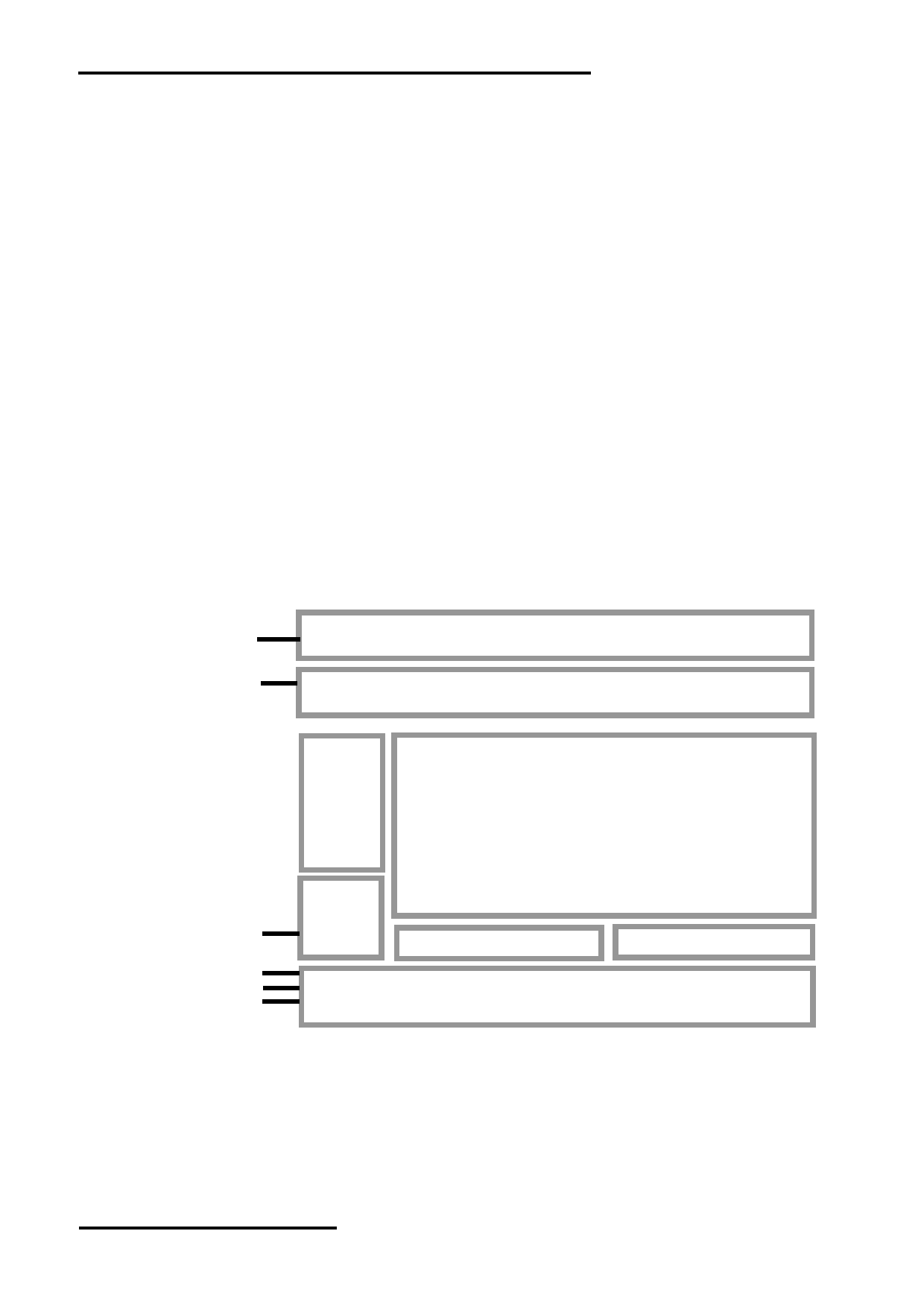
2. Block Diagram
4 Wire Touch Panel
YU,XL,YD,XR
VDD,GND
PWM,BRTC
Backlight Circuit
1024(x3) x 768 pixels
TFT Panel
Power
VCC
Ciruit
GND
Source Driver
Source Driver
D0+,D0-,D1+,D1-
D2+,D2-,D3+,D3-
LVDS interface
CLK+,CLK-
REV,SEL6/8
NURL: www.topwaydisplay.com
Document Name: LMT150DNGFWD-NNA-1-Manual-Rev0.1
Page: 3 of 13

TOPWAY
LCD Module User Manual
LMT150DNGFWD-NNA-1
3. Terminal Function
3.1 K1 TFT Terminal
Pin No.
Pin Name
IO
Descriptions
Input data signal: 24bit
Input data signal:18bit
1
VCC
Power
2
VCC
Power
Power Supply
3
GND
Power Ground
Selection of scan direction
4
REV
Input
High: Reverse scan
Low or Open: Normal scan
5
D0-
Input
LVDS receiver negative signal channel 0
6
D0+
Input
LVDS receiver positive signal channel 0
7
GND
Power Ground
8
D1-
Input
LVDS receiver negative signal channel 1
9
D1+
Input
LVDS receiver positive signal channel 1
10
GND
Power Ground
11
D2-
Input
LVDS receiver negative signal channel 2
12
D2+
Input
LVDS receiver positive signal channel 2
13
GND
Power Ground
14
CLK-
Input
LVDS receiver negative signal clock
15
CLK+
Input
LVDS receiver positive signal clock
16
GND
Power Ground
17
D3-
Input
LVDS receiver negative
signal channel 3
Ground
18
D3+
Input
LVDS receiver positive signal
channel 3
19
NC
--
Non connection
20
SEL6/8
Input
Low
High or Open
Note: Terminal header 185083-20121 ( P-TWO ELECTRIC TECHNOLOGY CO., LTD.) or equivalent
3.2 K2 Backlight Terminal
Pin No.
Pin Name
IO
Descriptions
1
NC
--
Non connection
PWM
Input
PWM Luminance control
2
BLADJ= Hi,100% Drive
BLADJ= Lo,0% Drive
3
BRTC
Input
Back light ON/OFF control:5V-On / 0V-Off
4
GND
Power Ground
5
VDD
Power Backlight Power Supply(12V)
Note: Terminal header MSB24038P5 (Produced by STM) or equivalent
3.3 Touch Panel Terminal
Pin No.
Pin Name
IO
Descriptions
1
XR
Passive Right Side sense Terminal
2
YU
Passive Up Side sense Terminal
3
XL
Passive Left Side sense Terminal
4
YD
Passive Down Side sense Terminal
NURL: www.topwaydisplay.com
Document Name: LMT150DNGFWD-NNA-1-Manual-Rev0.1
Page: 4 of 13

TOPWAY
LCD Module User Manual
LMT150DNGFWD-NNA-1
4. Absolute Maximum Ratings
GND=0V
Items
Symbol
Min.
Max.
Unit
Condition
Power voltage
VCC
-0.5
5.0
V
Input voltage
V IN
-0.5
5.0
V
Operating Temperature
T OP
-20
70
℃
Note1
Storage Temperature
T ST
-30
80
℃
Relative Humidity(*2)
RH
--
≤ 90
%
Ta ≤ 40 ℃
--
≤ 85
%
40 ℃< Ta ≤ 50 ℃
--
≤ 55
%
50 ℃< Ta ≤ 60 ℃
--
≤ 36
%
60 ℃< Ta ≤ 70 ℃
--
≤ 24
%
70 ℃< Ta ≤ 80 ℃
Absolute Humidity
AH
--
≤ 70
g/m ³
Ta > 50 ℃
Note:
*1. The temperature of panel display surface area should be -20 ° C Min and 70 ° C Max.
*2: a).Ta means the ambient temperature.
b).It is necessary to limit the relative humidity to the specified temperature range.
c).Condensation on the module is not allowed.
d).Wet-bulb temperature should be39 ° C Max. (Ta> 40 ° C)
e).90%RH Max. (Ta ≤ 40 ° C)
*3. Any Stresses exceeding the Absolute Maximum Ratings may cause substantial damage to the device.
Functional operation of this device at other conditions beyond those listed in the specification is not implied and
prolonged exposure to extreme conditions may affect device reliability.
NURL: www.topwaydisplay.com
Document Name: LMT150DNGFWD-NNA-1-Manual-Rev0.1
Page: 5 of 13

TOPWAY
LCD Module User Manual
LMT150DNGFWD-NNA-1
5. Electrical Characteristics
5.1 DC Characteristics
VCC=3.3V,GND=0V,Ta=25 ℃
Items
Symbol
MIN.
TYP.
MAX.
Unit
Note
Power supply voltage
VCC
3.0
3.3
3.6
V
Power supply ripple
Vp-p
200
mA Including
spike noise
Power supply current
I CC
--
550
--
mA *1
Permissible ripple voltage
VRP
--
--
100
mV
Differential input voltage
︱ Vid ︱
250
--
450
mV
Differential input
High
VTH
--
--
100
mV VCM = 1.25V
threshold voltage for
Low
VTL
-100
--
--
mV *2
LVDS receiver
Input voltage width for LVDS
Vi
0
--
1.90
V
receiver
Terminating resistor
RT
--
100
-
Ω
Rush current
I rush
--
-
1.5
A
*3
Input voltage for
High
VFH
0.7VCC
--
VCC
V
MSL signals
Low
VFL
0
---
0.3VCC
V
Note:
*1: Black mode, 65MHz, at VCC = 3.3V.
*2: Common mode voltage for LVDS receiver.
*3: Measurement Conditions.
5.2 Driving For Backlight
Items
Symbol
MIN.
TYP.
MAX.
Unit
Note
Power supply voltage
VDD
10.8
12.0
12.6
V
Power supply current
IDD
--
705
--
mA
Input voltage for
High
VDFH1
2.0
--
5.0
V
BLADJ signal
Low
VDFL1
0
--
0.4
V
Input voltage for
High
VDFH2
2.0
--
5.0
V
BLEN signal
Low
VDFL2
0
--
0.4
V
PWM frequency
fpwm
200
--
(20K)
Hz
BLADJ
PWM duty
--
5
--
100
%
BLADJ
Led life time
Hr
--
50000
--
Hour
*1
Note:
*1. Optical performance should be evaluated at Ta=25 ℃ .
5.3 Touch Panel Characteristics
Items
MIN.
TYP.
MAX.
Unit
Note
Operating Voltage
--
--
10
V
150
400
1100
Ω
X-terminal
Terminal resistance
150
400
1100
Ω
Y-terminal
Operating pressure
20
--
150
g
Response time
--
--
10
ms
Life Time
--
1000,000
--
Click Times
NURL: www.topwaydisplay.com
Document Name: LMT150DNGFWD-NNA-1-Manual-Rev0.1
Page: 6 of 13

TOPWAY
LCD Module User Manual
LMT150DNGFWD-NNA-1
5.4 Block Diagram
*1.Relations between GND (Signal ground and LED driver ground) and FG (Frame ground)
in the LCD module are as follows
GND - FG
Connected
*2. GND and FG must be connected to customer equipment’s ground, and it is
recommended that these grounds be connected together in customer equipment.
NURL: www.topwaydisplay.com
Document Name: LMT150DNGFWD-NNA-1-Manual-Rev0.1
Page: 7 of 13

TOPWAY
LCD Module User Manual
LMT150DNGFWD-NNA-1
6. Display colors and input data information
6.1
Display colors and data signal
This product can display in equivalent to 16,194,277 colors in 253 scales. Also the relation
between display colors and input data signals is as the following table. And it can display in
equivalent to 262,144 colors in 64 scales, without data signals R7, R6, G7, G6, B7, B6 in the
following table.
NURL: www.topwaydisplay.com
Document Name: LMT150DNGFWD-NNA-1-Manual-Rev0.1
Page: 8 of 13

TOPWAY
LCD Module User Manual
LMT150DNGFWD-NNA-1
6.2
Data mapping
(1) LVDS Input data signal: 24bit(VESA mode)
(2) LVDS Input data signal: 18bit
NURL: www.topwaydisplay.com
Document Name: LMT150DNGFWD-NNA-1-Manual-Rev0.1
Page: 9 of 13

TOPWAY
LCD Module User Manual
LMT150DNGFWD-NNA-1
7. AC Characteristics
7.1
Timing Characteristics
Parameter
Symbol
MIN.
TYP.
MAX. Unit
Unit
Clock
Frequency
1/tc
52
56.88
71
MHz
17.58ns
(typ)
tc
19.23
17.58
14.08
Ns
Horizontal
Cycle
th
1114
1200
1400
CLK
signals
Display period
thd
1024
Vertical
Cycle
tv
778
790
845
H
60.0Hz(typ)
signals
Display period
tvd
768
-
7.2
Input signal timing chart
NURL: www.topwaydisplay.com
Document Name: LMT150DNGFWD-NNA-1-Manual-Rev0.1
Page: 10 of 13

TOPWAY
LCD Module User Manual
LMT150DNGFWD-NNA-1
7.3
Pixel data alignment of display Image
The following chart is the coordinates of per pixel
Note :
*1.Pixel arrangement is BGR strip when module’s PCB side placed upward. It is suggested that
Module’s PCB side should place downward to compatible with RGB pixel arranging modules.
7.4
Power supply voltage sequence
6.4.1 The sequence of backlight and power
NURL: www.topwaydisplay.com
Document Name: LMT150DNGFWD-NNA-1-Manual-Rev0.1
Page: 11 of 13

TOPWAY
LCD Module User Manual
LMT150DNGFWD-NNA-1
8. Optical Characteristics
VDD=12V,VCC=3.3V,GND=0V,Ta=25 ℃
Item
Symbol
Condition
MIN.
TYP.
MAX.
UNIT
Note.
θ L
9 o’clock
70
80
-
Viewing angle
θ R
3 o’clock
70
80
-
(CR ≥ 10)
degree
*2
θ T
12 o’clock
70
80
-
θ B
6 o’clock
70
80
-
T ON
-
8
12
msec
Response Time
*3
T OFF
-
8
12
msec
Contrast ratio
CR
600
800
-
-
Normal
W X
0.263
0.313
0.363
-
*1
Color chromaticlty
θ=0 o
W Y
0.279
0.329
0.379
-
Luminance
L
320
360
-
cd/m 2
*4
Luminance uniformity
Y U
-
75
80
%
*4
Note:
*1. Definition of Contrast Ratio
The contrast ratio could be calculate by the following expression:
Contrast Ratio (CR) = Luminanc with all pixels white / Luminance with all pixels black
*2 Definition of Viewing Angle
*3 Definition of response time
*4 Definition of Luminance Uniformity
Luminance uniformity (Lu)=
Min. Luminance form pt1~pt9 / Max Luminance form Pt1~pt9
NURL: www.topwaydisplay.com
Document Name: LMT150DNGFWD-NNA-1-Manual-Rev0.1
Page: 12 of 13

TOPWAY
LCD Module User Manual
LMT150DNGFWD-NNA-1
9. Touch panel Design Precautions
1. It should prevent front case touching the touch
panel Active Area (A.A.) to prevent abnormal
touch.
It should left gab (e.g. 0.2~0.3mm) in between.
2. Outer case design should take care about the area outside the A.A.
Those areas contain circuit wires which is having different thickness. Touching those areas could de-
form the ITO film. As a result case the ITO cold be damaged and shorten its lifetime.
It is suggested to protect those areas with gasket (between the front case and the touch panel).
The suggested figures are B≥0.50mm; C≥0.50mm 。
3. The front case side wall should keep space
(e.g. 0.2 ~ 0.3mm) from the touch panel.
4. I In general design,
touch panel V.A. should be bigger than the LCD V.A.
and touch panel A.A. should be bigger than the LCD A.A.
10. Precautions for Use of LCD Modules
Please refer to "LCD-Module-Design-Handling-Precaution.pdf".
NURL: www.topwaydisplay.com
Document Name: LMT150DNGFWD-NNA-1-Manual-Rev0.1
Page: 13 of 13