HKT070ETA-D
LCD Module User Manual
Prepared by:
Checked by:
Approved by:
HeHongLiang
Date: 2024-06-06
Date:
Date:
Rev. Descriptions
Edit
Release Date
0.1
- Preliminary Draft release
Chenzhonghua
2024-03-08
0.2
-Add TFT QA Standard
Chenzhonghua
2024-03-14
0.3
-Refine Outline
HeHongLiang
2024-06-06
URL: www.topwaydisplay.com
Document Name: HKT070ETA-D-Manual-Rev0.3.doc
Page: 1 of 12

TOPWAY
LCD Module User Manual
HKT070ETA-D
Table of Content
1 Basic Specification .......................................................................................................................................... 3
1.1 General Specification..................................................................................................................................3
1.2 Block Diagram.............................................................................................................................................3
1.3 Terminal Function....................................................................................................................................... 4
2 Absolute Maximum Ratings ............................................................................................................................4
3 Electrical Characteristics ................................................................................................................................5
3.1 DC Characteristics ...................................................................................................................................... 5
4 Function Specifications .................................................................................................................................. 5
4.1 Basic Operation Function Descriptions .......................................................................................................5
4.2 Quick Start Guide........................................................................................................................................6
4.3 Command Descriptions ...............................................................................................................................6
5 Optical Characteristics ....................................................................................................................................7
6 Precautions of using LCD Modules ............................................................................................................... 9
7 Assemble Precaution .................................................................................................................................... 10
8 TFT QA Standard ............................................................................................................................................11
8.1 INSPECTION CONDITION 检验条件 ...................................................................................................... 11
8.2 Display Pattern 显示缺陷 .......................................................................................................................... 11
8.3 Quality Level and Sampling 抽样方法 .......................................................................................................12
9 Warranty..........................................................................................................................................................12
URL: www.topwaydisplay.com
Document Name: HKT070ETA-D-Manual-Rev0.3.doc
Page: 2 of 12
TOPWAY
LCD Module User Manual
HKT070ETA-D
1 Basic Specification
TOPWAY HKT070ETA-D is a Smart TFT Module with 32bit MCU on board. Its graphics engine provides
numbers of outstanding features. It supports TOPWAY SGTools for preload and pre-design display
interface that simplify the host operation and development time. Suitable for industry control,
instrumentation, medical electronics, power electric equipment applications.
1.1 General Specification
Screen Size(Diagonal) :
7”
Resolution :
800(RGB) x 480
Color Depth :
65k color (16bit)
Pixel Configuration :
RGB Stripe
Display Mode :
Transmissive / Normal White
Viewing Direction :
6H(*1)(gray-scale inverse)
12H(*2)
Outline Dimension :
200.0 x 125.0 x 33.7 (max)(mm)
(see attached drawing for details)
Active Area :
154.08 x 85.92(mm)
Backlight :
LED
Command I/F:
RS-232C
Touch Panel Type:
Capacitive Touch Panel
Project Download:
by PC or by U-Drive (with OTG cable)
Operating Temperature :
-25 ~ +70°C
Storage Temperature :
-30 ~ +80°C
Highlight :
RTC without battery,Casing,Support 90 degrees rotation,
Lua script engine, Buzzer ,256MB Flash
Note:
*1. For saturated color display content (eg. pure-red, pure-green, pure-blue, or pure-colors-combinations).
*2. For “color scales” display content.
*3. Color tone may slightly change by Temperature and Driving Condition.
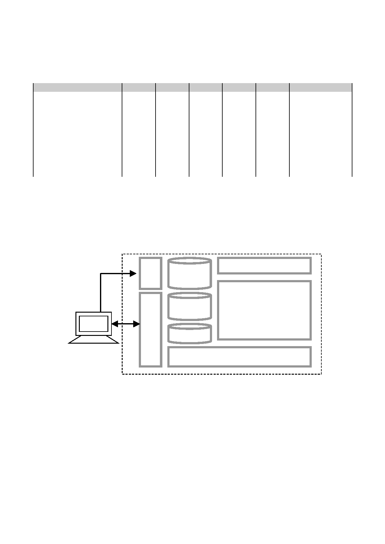
1.2 Block Diagram
Touch Panel
7" TFT
800 x 480 pixels
K1
RTS(BUSY)
TX, RX
Display Function Controller
VDD, VSS
with RTC
K2
ID, D-, D+
Flash
Memory
RAM
VUSB, VSS
URL: www.topwaydisplay.com
Document Name: HKT070ETA-D-Manual-Rev0.3.doc
Page: 3 of 12
TOPWAY
LCD Module User Manual
HKT070ETA-D
1.3 Terminal Function
RS232 Interface Terminal (K1)
Pin No.
Pin Name
I/O Descriptions
1
VSS
P
Ground, (0V)
2
NC
--
No connection, leave open
3
RTS(BUSY)
O
Request To Send (could function as busy BUSY signal)
(eg. to PC’s RS232C pin8 <9pin D-connector> )
4
TX
O
Data output (eg. to PC’s RS232C pin2 <9pin D-connector>)
5
RX
I
Data Input
(eg. to PC’s RS232C pin3 <9pin D-connector>)
6
VDD
P
Power supply (11.0 ~ 26.0)
Note.
*1. User data and commands transfer through this terminal.
*2. HOST using command hand shake during communication is suggested.
USB Interface Terminal (K2)
Pin No.
Pin Name
I/O Descriptions
1
VUSB
P
Power supply (5V)
2
D-
I/O
USB DATA negative signal
3
D+
I/O
USB DATA positive signal
4
ID
I
USB_ID, 1:Client , 0:HOST
5
VSS
P
Ground, (0V)
Note.
*1. TML files and image files preload through this terminal
*2. Standard “USB-drive” functions provided
*3. During the files transfer, all others display functions will be suspended
2 Absolute Maximum Ratings
Items
Symbol
Min.
Max.
Unit
Condition
Power Supply voltage
V dd
-0.3
26.0
V
TX Out voltage
V Tx
-13.2
+13.2
V
RX Input voltage
V Rx
-25
+25
V
Operating Temperature
T OP
-25
70
C
No Condensation
Storage Temperature
T ST
-30
80
C
No Condensation
Note:
*1. This rating applies to all parts of the module and should not be exceeded.
*2. The operating temperature only guarantees operation of the circuit. The contrast, response speed,
and the other specification related to electro-optical display quality is determined at the room temperature, T OP =25 ℃
*3. Ambient temperature when the backlight is lit (reference value)
*4. Any Stresses exceeding the Absolute Maximum Ratings may cause substantial damage to the device. Functional
operation of this device at other conditions beyond those listed in the specification is not implied and prolonged
exposure to extreme conditions may affect device reliability.
URL: www.topwaydisplay.com
Document Name: HKT070ETA-D-Manual-Rev0.3.doc
Page: 4 of 12
TOPWAY
LCD Module User Manual
HKT070ETA-D
3 Electrical Characteristics
3.1 DC Characteristics
VSS=0V, VDD=12V, T OP =25 C
Items
Symbol
MIN.
TYP.
MAX.
Unit
Applicable Pin
Operating Voltage
V DD
11.0
12.0
26.0
V
VDD
Rx Input MARK(1)
V RxM
-3.0
-
-15.0
V
Rx
Rx Input SPACE(0)
V R X S
+3.0
-
+15.0
V
Rx
Tx Output MARK(1)
V T X M
-3.0
-
-15.0
V
Tx
Tx Output SPACE(0)
V T X S
+3.0
-
+15.0
V
Tx
RTS Output High
V TXH
-3.0
-
-15.0
V
RTS(BUSY)
RTS Output Low
V TXL
+3.0
-
+15.0
V
RTS(BUSY)
Operating Current
I DD
-
TBD
-
mA
VDD (*1)
Operating Current (USB)
I VUSB
-
TBD
-
mA
VUSB
Battery Supply current
I BAT
-
2
-
uA
Note.
*1. Normal display condition,VDD=12V.
4 Function Specifications
4.1 Basic Operation Function Descriptions
HKT070ETA-D
Capacitive Touch Panel
TML files
Picture files
ICONS files
Custom
Memories
TFT Display
HOST
PC
VP variables
Control and Draw Engine
- TML files, Picture files, ICON files are stored inside FLASH memory area.
They are preloaded to HKT070ETA-D for stand alone interface use.
- Those files are preloaded via USB interface as an USB drive.
- All the interface flow and the touch response are based on the preloaded TML files
- VP variables memory is inside RAM area,
it provides real time access via UART by the HOST or display onto the TFT by TML file.
- Custom Memories are inside FLASH memory area
It can be accessed via UART interface by the HOST.
- Control and Draw Engine executes HOST commands and response respectively
- It also reports the real time Touch Key number to the HOST
URL: www.topwaydisplay.com
Document Name: HKT070ETA-D-Manual-Rev0.3.doc
Page: 5 of 12
TOPWAY
LCD Module User Manual
HKT070ETA-D
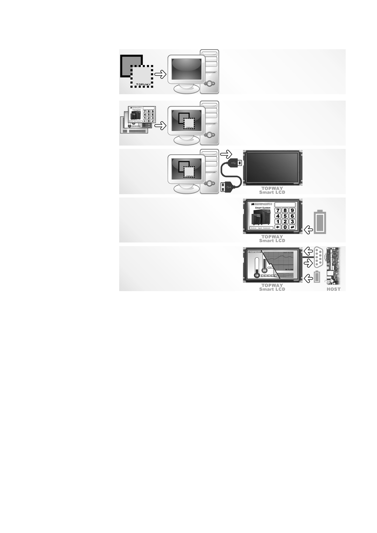
4.2 Quick Start Guide
1.
Install TOPWAY
Graphics Editor
Import pictures
2. design UI flow
3.
Download to
Smart LCD
4. power on &
display
Connect to
5.
host Show
real time
data
4.3 Command Descriptions
Please refer to “SMART LCD Command Manual” .
URL: www.topwaydisplay.com
Document Name: HKT070ETA-D-Manual-Rev0.3.doc
Page: 6 of 12

TOPWAY
LCD Module User Manual
HKT070ETA-D
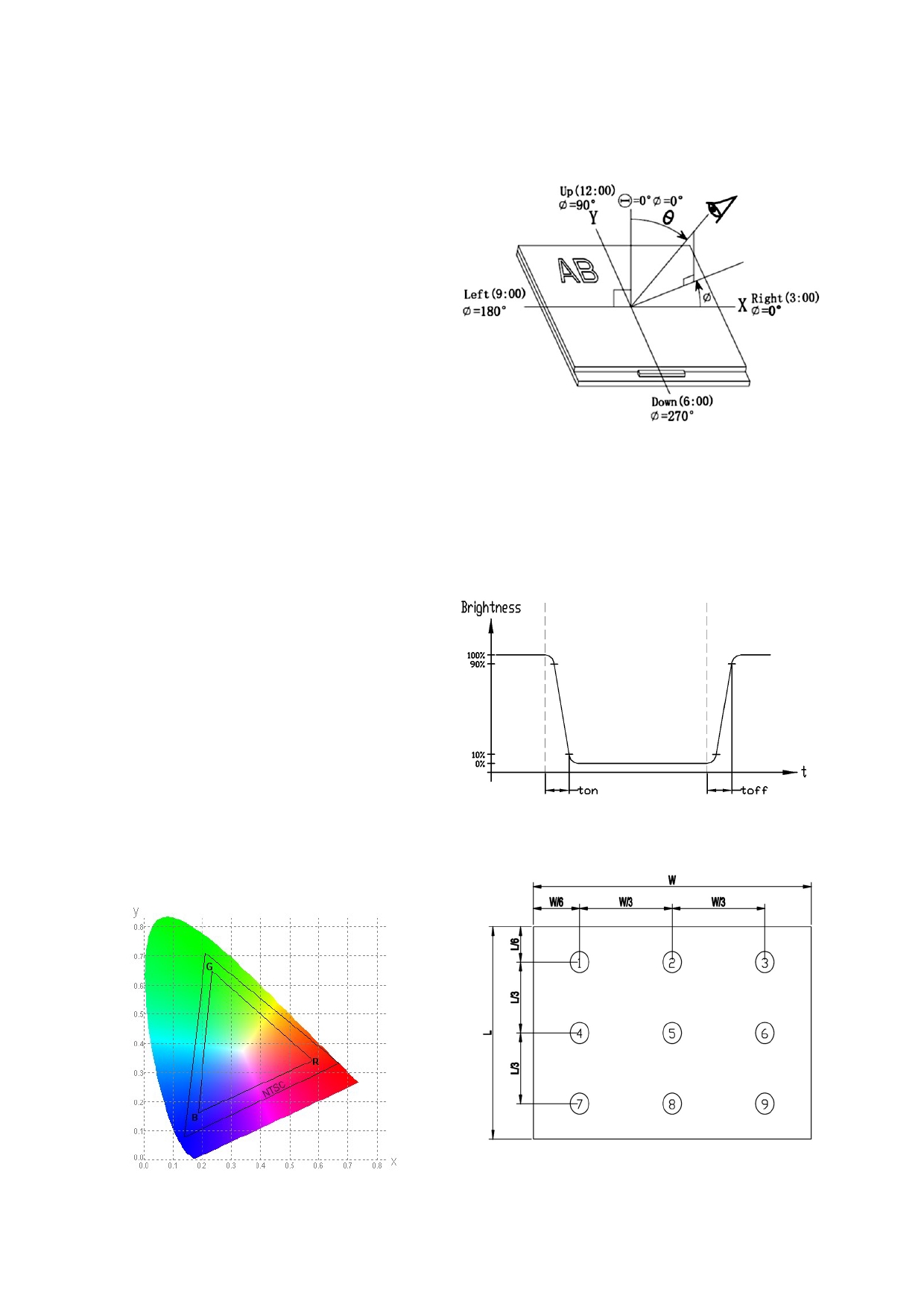
5 Optical Characteristics
Item
Symbol Condition
Min
Typ
Max
Unit
Remark
θT
70
80
-
View Angles
θB
CR ≧ 10
50
60
-
Degree Note2,3
θL
70
80
-
θR
70
80
-
Contrast Ratio
CR
θ =0 °
700
900
-
Note 3
T ON
Response Time
25 ℃
-
20
30
ms
Note 4
T OFF
x
0.255
0.305
0.355
White
Note 1,5
y
0.277
0.327
0.377
x
0.534
0.584
0.634
Red
Note 1,5
Chromaticity
Backlight is
y
0.300
0.350
0.400
x
on
0.290
0.340
0.390
Green
Note 1,5
y
0.543
0.593
0.643
x
0.102
0.152
0.202
Blue
Note 1,5
y
0.040
0.090
0.140
Uniformity
U
75
80
-
%
Note 6
NTSC
45
50
-
%
Note 5
Luminance
L
-
500
-
cd/ ㎡ Note 7
1. The ambient temperature is 25 ℃ .
2. The test systems refer to Note 1 and Note 2.
URL: www.topwaydisplay.com
Document Name: HKT070ETA-D-Manual-Rev0.3.doc
Page: 7 of 12
TOPWAY
LCD Module User Manual
HKT070ETA-D
Note 1:
Note 2:
The data are measured after LEDs are turned on for 5 minutes.
The definition of viewing angle:
LCM displays full white. The brightness is the average value of 9 Refer to the graph below marked by θ and Ф
measured spots. Measurement equipment SR-3A (1°)
Measuring condition:
- Measuring surroundings: Dark room
- Measuring temperature: Ta=25 ℃ .
- Adjust operating voltage to get optimum contrast at
the center of the display.
Note 3:
The definition of contrast ratio (Test LCM using SR-3A (1°)):
Note 4:
Contrast
Luminance When LCD is at “White” state
Definition of Response time. (Test LCD using BM-7A(2°)):
Ratio(CR)
=
Luminance When LCD is at “Black” state
The output signals of photo detector are measured
(Contrast Ratio is measured in optimum common electrode
when the input signals are changed from
voltage)
“black” to “white”(falling time)
and from “white” to “black”(rising time), respectively.
The response time is defined as
the time interval between the 10% and 90% of amplitudes.Refer to
figure as below.
Note 5:
Note 6:
Definition of Color of CIE1931 Coordinate and NTSC Ratio.
The luminance uniformity is calculated by using following formula.
△ Bp = Bp (Min.) / Bp (Max.)×100 (%)
Color gamut:
Bp (Max.) = Maximum brightness in 9 measured spots
Area of RGB triangle
S=
X100%
Bp (Min.) = Minimum brightness in 9 measured spots .
Area of NTSC triangle
Note 7:
Measured the luminance of white state at center point
URL: www.topwaydisplay.com
Document Name: HKT070ETA-D-Manual-Rev0.3.doc
Page: 8 of 12

TOPWAY
LCD Module User Manual
HKT070ETA-D
6 Precautions of using LCD Modules
Mounting
- Mounting must use holes arranged in four corners or four sides.
- The mounting structure so provide even force on to LCD module. Uneven force (ex. Twisted stress)
should not applied to the module. And the case on which a module is mounted should have sufficient
strength so that external force is not transmitted directly to the module.
- It is suggested to attach a transparent protective plate to the surface in order to protect the polarizer. It
should have sufficient strength in order to the resist external force.
- The housing should adopt radiation structure to satisfy the temperature specification.
- Acetic acid type and chlorine type materials for the cover case are not desirable because the former
generates corrosive gas of attacking the polarizer at high temperature and the latter causes circuit
break by electro-chemical reaction.
- Do not touch, push or rub the exposed polarizers with glass, tweezers or anything harder than HB
pencil lead. Never rub with dust clothes with chemical treatment. Do not touch the surface of polarizer
for bare hand or greasy cloth.(Some cosmetics deteriorate the polarizer.)
- When the surface becomes dusty, please wipe gently with absorbent cotton or other soft materials like
chamois soaks with petroleum benzine. Normal-hexane is recommended for cleaning the adhesives
used to attach front / rear polarizers. Do not use acetone, toluene and alcohol because they cause
chemical damage to the polarizer.
- Wipe off saliva or water drops as soon as possible. Their long time contact with polarizer
Operating
- The spike noise causes the mis-operation of circuits. It should be within the ± 200mV level (Over and
under shoot voltage)
- Response time depends on the temperature.(In lower temperature, it becomes longer.)
- Brightness depends on the temperature. (In lower temperature, it becomes lower.) And in lower
temperature, response time(required time that brightness is stable after turned on) becomes longer.
- Be careful for condensation at sudden temperature change. Condensation makes damage to polarizer
or electrical contacted parts. And after fading condensation, smear or spot will occur.
- When fixed patterns are displayed for a long time, remnant image is likely to occur.
- Module has high frequency circuits. Sufficient suppression to the electromagnetic interference shall be
done by system manufacturers. Grounding and shielding methods may be important to minimized the
interference
Electrostatic Discharge Control
Since a module is composed of electronic circuits, it is not strong to electrostatic discharge. Make certain
that treatment persons are connected to ground through wrist band etc. And don’t touch interface pin
directly.
Strong Light Exposure
Strong light exposure causes degradation of polarizer and color filter.
Storage
When storing modules as spares for a long time, the following precautions are necessary.
- Store them in a dark place. Do not expose the module to sunlight or fluorescent light. Keep the
temperature between 5 ° C and 35 ° C at normal humidity.
- The polarizer surface should not come in contact with any other object. It is recommended that they
be stored in the container in which they were shipped.
Protection Film
- When the protection film is peeled off, static electricity is generated between the film and polarizer.
This should be peeled off slowly and carefully by people who are electrically grounded and with well
ion-blown equipment or in such a condition, etc.
- The protection film is attached to the polarizer with a small amount of glue. If some stress is applied to
rub the protection film against the polarizer during the time you peel off the film, the glue is apt tore
main on the polarizer. Please carefully peel off the protection film without rubbing it against the
polarizer.
- When the module with protection film attached is stored for a long time, sometimes there remains a
very small amount of glue still on the polarizer after the protection film is peeled off.
- You can remove the glue easily. When the glue remains on the polarizer surface or its vestige is
recognized, please wipe them off with absorbent cotton waste or other soft material like chamois
soaked with normal-hexane.
Transportation
The LCD modules should be no falling and violent shocking during transportation, and also should avoid
excessive press, water, damp and sunshine.
URL: www.topwaydisplay.com
Document Name: HKT070ETA-D-Manual-Rev0.3.doc
Page: 9 of 12
TOPWAY
LCD Module User Manual
HKT070ETA-D
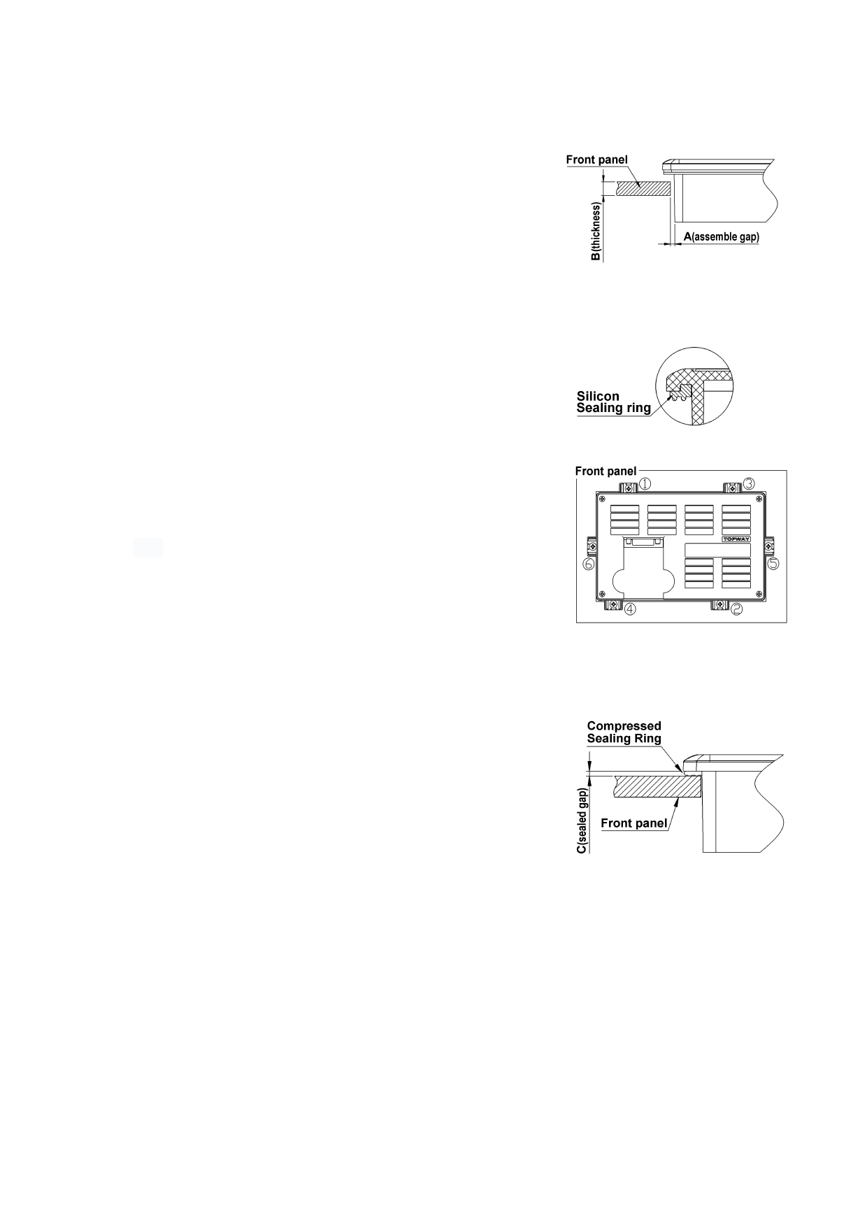
7 Assemble Precaution
安装注意事项
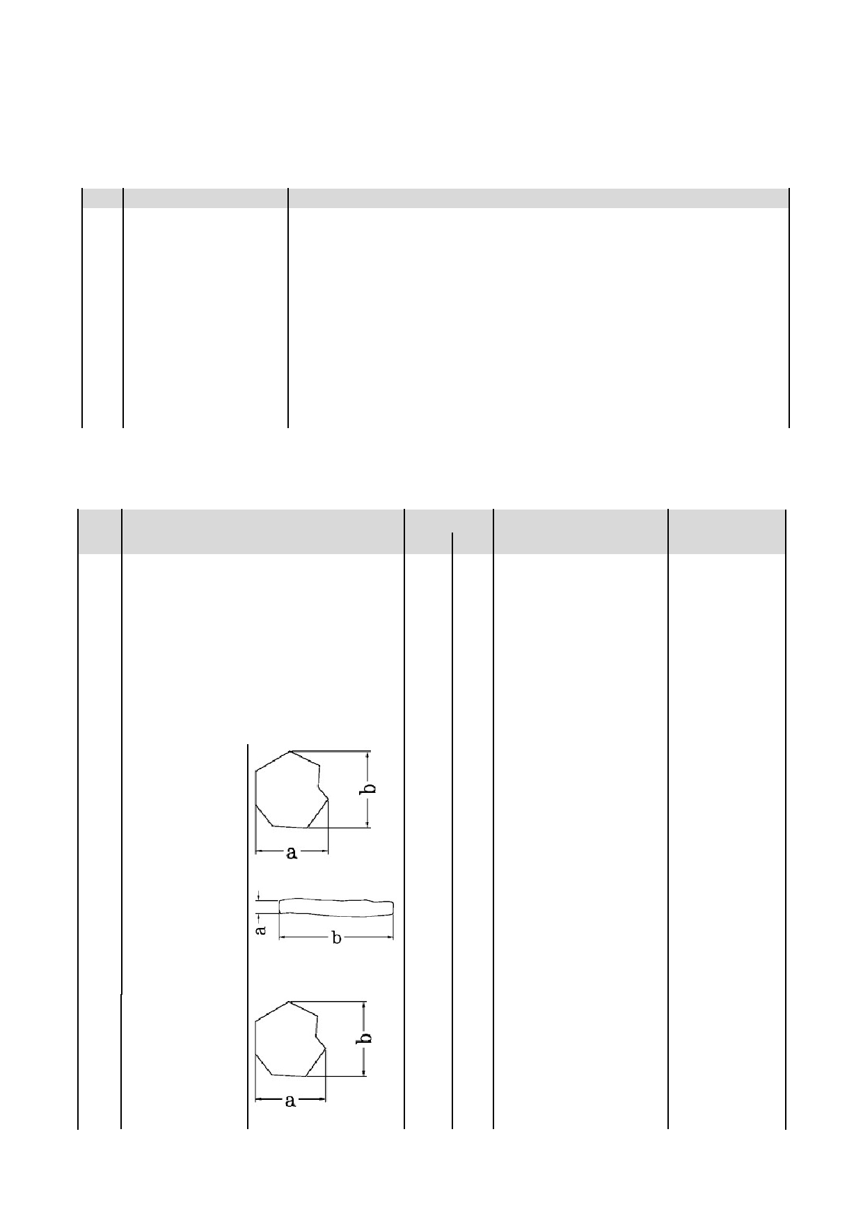
1. Customer front panel opening and thickness for TOPWAY
display module should be fit for its assembling and sealing.
The suggested assemble gap(A) should be about
0.3~0.5mm on each side.
The suggested front panel thickness(B) should be about
1.5~4.0mm.
客户面板开窗及厚度应适合 TOPWAY 显示模块的安装及密封 .
2. A silicon sealing ring ships with TOPWAY display module. It
should be in place before assembling to the front panel.
TOPWAY 显示模块上的硅胶密封圈在安装时确保嵌入到位 .
3. It should fix the TOPWAY display module into the front panel
with two steps.
Pre-fixing: Slightly tighten the screws on beam clamp in
sequence as picture on the right side.
Final-fixing: Tighten the fixing screws on beam clamp in
sequence as well with twist torque about 6~8kg.cm (*1) .
and put the beam clamp straight.
Note:
*1. Over tightening might damage the shell and cause bad sealing result.
应分两步将 TOPWAY 显示模块固定在面板上 .
意卡扣置正无歪斜 .
注 :
*1. 过度拧紧可能会损坏外壳和影响密封效果 .
4. It is strongly suggested to check the seal balancing of the
four-side of the TOPWAY display module.
The suggested after assemble sealed gap(C) should be
about 1.0~1.5mm.
需注意检查 TOPWAY 显示模块四周在安装后保证平衡密封 .
5. Others:
Never hot plug the device! Power off the device before connect or disconnect the display
module.
Don't forget to remove the cover protective film for normal operation.
其它 :
URL: www.topwaydisplay.com
Document Name: HKT070ETA-D-Manual-Rev0.3.doc
Page: 10 of 12
TOPWAY
LCD Module User Manual
HKT070ETA-D
8 TFT QA Standard
8.1 INSPECTION CONDITION 检验条件
Unless otherwise stated , all the inspections are carryout under the following condition
除非有特别的规定,检验条件按以下执行。
No. Items 项目
Conditions 条件
1
Lighting
Illumination: Appearance 200-500Lux
照明
环境亮度在 300~700LUX
2
Inspection Distance
30-40cm form the test sample , within normal viewing angle
检验距离
眼睛距显示器表面 30~40cm
3
Temperature
Room Temperature (25 ºC), no condensation
环境温度
室温( 25 度 ±5% ),无凝水
4
Viewing Angle
U/D: 45º/45º, L/R: 45º/45º
视角
前后 45 度角范围内,左右 45 度角范围内
5
Inspection Time
15 seconds
检验时间
15 秒内
6
Defect Allowance
6 max
缺陷总数
允许 6 个
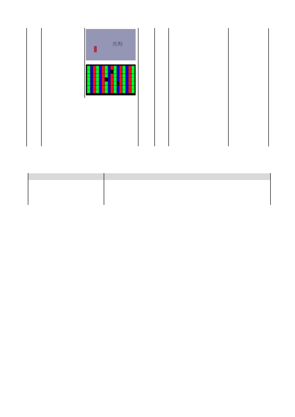
8.2 Display Pattern 显示缺陷
Type 类别
No. Items /Contents 检查项目
MA
MI Standard 标准
Judgment 判定
1
No Display
√
--
Not Allowed
无显示
不允许
2
Line defect
√
--
Not Allowed
缺少行或列
不允许
3
Display abnormally
√
--
Not Allowed
错误的显示
不允许
4
Function Defective
√
--
Not Allowed
缺少功能
不允许
5
Glass Crack
√
--
Not Allowed
玻璃破碎
不允许
Spot Defect
√
(a+b)/2≤0.25
Allowed
6
Including:
允许
Black spot,
White spot
0.25<(a+b)/2≤0.5
4 max.
Foreign particle,
允许 4 个
Polarizer dirt,
Cell particle
(a+b)/2 > 0.5
Not Allowed
黑点 / 白点
不允许
7
Line Defect
√
a≤0.1
Allowed
Including:
允许
Black line,
0.1<a≤0.2 and b≤5.0
4max.
White line,
允许 4 个
Scratch
Not Allowed
线
a > 0.2 or b > 5.0
不允许
8
Polarizer
√
(a+b)/2≤0.3
Allowed
Dent/Bubble
允许
偏光片气泡
0.3< (a+b)/2≤0.6
3 max.
允许 3 个
(a+b)/2>0.7
Not Allowed
不允许
URL: www.topwaydisplay.com
Document Name: HKT070ETA-D-Manual-Rev0.3.doc
Page: 11 of 12
TOPWAY
LCD Module User Manual
HKT070ETA-D
9
Bright dot defect
√
Random
2 max.
允许 2 个
亮点
3 consecutive dots
Not Allowed
( 在全黑屏下多像
3 个或以上连续的点
不允许
素点)
10
Dark dot defect
√
Random
4 max.
允许 4 个
暗点
3 consecutive dots
Not Allowed
(在全红或全绿或
3 个或以上连续的点
不允许
全蓝屏下缺像素
点)
13
Bright dot defect + Dark dot defect
√
--
4 max.
亮点 + 暗点
允许 4 个
14
FPC or FFC broken
√
--
Not Allowed
FPC/FFC 损坏
不允许
15
PCBA defect
--
--
Refer to IPC-A-610
--
PCBA 缺陷
按照 IPC-A-610
√
8.3 Quality Level and Sampling 抽样方法
Items 项目
Standard 标准
Sampling Standard 引用标准
MIL-STD-105E
Sampling Level 抽样等级
Ⅱ
AQL level 合格判定水平
MA: AQL=0.65
MI: AQL=1.0
9 Warranty
This product has been manufactured to our company’s specifications as a part for use in your company’s general
electronic products. It is guaranteed to perform according to delivery specifications. For any other use apart from general
electronic equipment, we cannot take responsibility if the product is used in medical devices, nuclear power control
equipment, aerospace equipment, fire and security systems, or any other applications in which there is a direct risk to
human life and where extremely high levels of reliability are required. If the product is to be used in any of the above
applications, we will need to enter into a separate product liability agreement.
- We cannot accept responsibility for any defect, which may arise form additional manufacturing of the product
(including disassembly and reassembly), after product delivery.
- We cannot accept responsibility for any defect, which may arise after the application of strong external force to the
product.
- We cannot accept responsibility for any defect, which may arise due to the application of static electricity after the
product has passed our company’s acceptance inspection procedures.
- When the product is in CCFL models, CCFL service life and brightness will vary according to the performance of the
inverter used, leaks, etc. We cannot accept responsibility for product performance, reliability, or defect, which may
arise.
- We cannot accept responsibility for intellectual property of a third part, which may arise through the application of our
product to our assembly with exception to those issues relating directly to the structure or method of manufacturing of
our product.
URL: www.topwaydisplay.com
Document Name: HKT070ETA-D-Manual-Rev0.3.doc
Page: 12 of 12
SMART LCD
Command V6.12
Manual
Prepared by:
Checked by:
Approved by:
Date: 2023-11-13
Date:
Date:
Rev. Descriptions
Enactment/Revision Release Date
0.1
- Preliminary Draft release
2018-08-28
0.2
- add 0x94, 0x95
2018-11-22
0.3
- update section 2.1, 4.2.4, 4.2.7, 4.4.2, 4.4.9
chenjian
2019-06-28
0.4
- add 0x96,0x97,0xEE
liwenming
2023-11-13
URL: www.topwaydisplay.com
Document Name:SMART LCD Command v6.12 Manual Rev0.4.doc
www.topwaysz.com
Page: 1 of 23

TOPWAY
SMART LCD Command Manual
Protocol V6.12
Table of Content
1
Basic Specifications...................................................................................................................................4
1.1
Hardware connection............................................................................................................................4
2
Command Structure................................................................................................................................... 4
2.1
Communication Packet Structure......................................................................................................... 4
2.1.1 Basic Packet:.................................................................................................................................... 4
2.1.2 Packet with length:............................................................................................................................4
2.1.3 Packet with CRC:..............................................................................................................................4
2.2
Packet Timeout.....................................................................................................................................5
2.3
Packet Acknowledgment...................................................................................................................... 5
3
Data arrangement....................................................................................................................................... 5
3.1
Color Data Value Configuration............................................................................................................5
3.2
Data / Address / Page_ID / Location Values Configuration ................................................................. 5
4
Command Descriptions............................................................................................................................. 6
4.1
Command table.....................................................................................................................................6
4.2
Config/ Status Function Commands Details.........................................................................................7
4.2.1 hand_shake ( 0x30 )......................................................................................................................... 7
4.2.2 read_version ( 0x31 )........................................................................................................................7
4.2.3 read_pg_id ( 0x32 )...........................................................................................................................8
4.2.4 touch_response ( 0x72/ 0x73/ 0x77/ 0x78/ 0x79 )........................................................................... 8
4.2.5 set_sys_config ( 0xE0 ).................................................................................................................... 9
4.2.6 sel_project ( 0xE1 ).........................................................................................................................10
4.2.7 touch_calib ( 0xE4 )........................................................................................................................ 10
4.2.8 screen_saver (0x5E).......................................................................................................................10
4.2.9 backlight_ctrl ( 0x5F )..................................................................................................................... 10
4.2.10
buzzer_touch_sound ( 0x79 )..................................................................................................... 10
4.2.11
buzzer_ ctrl ( 0x7A )....................................................................................................................10
4.2.12
Flash_write ( 0x90 ).................................................................................................................... 11
4.2.13
Flash_read ( 0x91 ).....................................................................................................................11
4.2.14
USR_bin_read ( 0x93 )...............................................................................................................11
4.2.15
Ymodem_transmit ( 0x96 )......................................................................................................... 12
4.2.16
Checksum_calculate ( 0x97 )..................................................................................................... 12
4.2.17
RTC_read ( 0x9B )......................................................................................................................12
4.2.18
RTC_set ( 0x9C )........................................................................................................................12
4.2.19
U_drv_format ( 0xE2 )................................................................................................................ 13
4.2.20
U_drv_unlock ( 0xE3 )................................................................................................................ 13
4.2.21
Reset ( 0xEE)..............................................................................................................................13
4.3
Display Control Function Commands Details.....................................................................................13
4.3.1 disp_page ( 0x70 ).......................................................................................................................... 13
4.3.2 set_element_fg ( 0x7E )..................................................................................................................13
4.3.3 set_element_bg ( 0x7F ).................................................................................................................14
4.3.4 set_codepage (0xE7)......................................................................................................................14
4.3.5 suspend_vp_refresh (0xE8)............................................................................................................14
4.4
VP Function Commands Details.........................................................................................................14
4.4.1 Successive_write ( 0x82 )...............................................................................................................14
4.4.2 Successive_read ( 0x83 )............................................................................................................... 15
4.4.3 VP_Backup ( 0x94 )........................................................................................................................16
4.4.4 VP_Preload ( 0x95 )....................................................................................................................... 16
4.4.5 BP1_write ( 0x4B )..........................................................................................................................16
4.4.6 BP1_write_compress ( 0x4C )........................................................................................................17
4.4.7 G16_write ( 0x4D )..........................................................................................................................17
4.4.8 G16_write_rotate ( 0x4E )...............................................................................................................17
4.4.9 Reg_Write ( 0x3B )......................................................................................................................... 18
4.4.10
Reg_Read ( 0x3C ).....................................................................................................................18
4.4.11
STR_write ( 0x42 )......................................................................................................................18
4.4.12
STR_read ( 0x43 )...................................................................................................................... 19
4.4.13
STR_fill ( 0x46 ).......................................................................................................................... 19
4.4.14
N16_write ( 0x3D )......................................................................................................................19
4.4.15
N16_read ( 0x3E ).......................................................................................................................20
4.4.16
N16_fill ( 0x3F )...........................................................................................................................20
URL: www.topwaydisplay.com
Document Name:SMART LCD Command v6.12 Manual Rev0.4.doc
www.topwaysz.com
Page: 2 of 23

TOPWAY
SMART LCD Command Manual
Protocol V6.12
4.4.17
N32_write ( 0x44 ).......................................................................................................................20
4.4.18
N32_read ( 0x45 ).......................................................................................................................21
4.4.19
N32_fill ( 0x47 )...........................................................................................................................21
4.4.20
N64_write ( 0x48 ).......................................................................................................................21
4.4.21
N64_read ( 0x49 ).......................................................................................................................22
4.4.22
N64_fill ( 0x4A ).......................................................................................................................... 22
Appendix 1 : CRC Calculate............................................................................................................................23
URL: www.topwaydisplay.com
Document Name:SMART LCD Command v6.12 Manual Rev0.4.doc
www.topwaysz.com
Page: 3 of 23
TOPWAY
SMART LCD Command Manual
Protocol V6.12
1 Basic Specifications
TOPWAY Smart LCD serial command is for real-time control and access. Host machine get the data
which input through the Smart LCD interface or provide the data for display.
1.1 Hardware connection
Smart LCD serial UART interface are mainly base on RS232-C standard, by default, config as 8N1
115200bps.
2 Command Structure
2.1 Communication Packet Structure
TOPWAY SmartLCD offer 3 kinds of Communication Packet Structure, which can be defined in
editor project setting.
2.1.1 Basic Packet:
Seq
Code
Code type
Description
1
0xAA
Packet header 1byte
2
Cmd-code
Command
1byte
code
3
Par-data
Parameter or
(*1)
Data
4
0xCC
Packet tail
4byte
0x33
0xC3
0x3C
2.1.2 Packet with length:
Seq
Code
Code type
Description
1
0xAA
Packet header 1byte
2
Len
Packet length 2byte(*2)
3
Cmd-code
Command
1byte
code
4
Par-data
Parameter or
(*1)
Data
5
0xCC
Packet tail
4byte
0x33
0xC3
0x3C
2.1.3 Packet with CRC:
Seq
Code
Code type
Description
1
0xAA
Packet header 1byte
2
Len
Packet length 2byte(*2)
3
Cmd-code
Command
1byte
code
4
Par-data
Parameter or
(*1)
Data
5
0xCC
Packet tail
2byte
0x33
6
CRCL
2byte(*3)
CRCH
Note.
*1. Unless otherwise specified,
all the multi-byte values, data, address’ byte sequence are MSB first, LSB last.
*2. Packet length: from Seq3 to the end. (no. of byte)
*3. CRC Polynomial: x16+x15+x2+1, Calculate the CRC value from Seq3 to Seq5.Please refer to appendix 1.
URL: www.topwaydisplay.com
Document Name:SMART LCD Command v6.12 Manual Rev0.4.doc
www.topwaysz.com
Page: 4 of 23
TOPWAY
SMART LCD Command Manual
Protocol V6.12
2.2 Packet Timeout
TOPWAY SmartLCD support Timeout setting, which can be defined in editor project setting.
Timeout options: None, 1s, 2s, 3s, 5s, 10s, 20s. If timeout, The incomplete Packet will be discarded.
2.3 Packet Acknowledgment
Packet Acknowledgment is two byte in ASCII (module host):
Response
code Description
Command (in packet) executed and
":>" In ASCII
wait for next Command
(0x3a, 0x3e)
Command (in packet) error and
"!>" In ASCII
15B15B15B15B
wait for next Command
(0x21,0x3e)
Note.
*1. Packet Acknowledgement response to a valid packet only.
3 Data arrangement
3.1 Color Data Value Configuration
16 bit Color value
16 bit color value
R4 R3 R2 R1 R0 G5 G4 G3 G2 G1 G0 B4 B3 B2 B1 B0
High byte (MSB)
Low byte (LSB)
D7 D6 D5 D4 D3 D2 D1 D0 D7 D6 D5 D4 D3 D2 D1 D0
3.2 Data / Address / Page_ID / Location Values Configuration
64bit value
64 bit number value
D63…D56 D55…D48 D47…D40 D39..D32 D31…D24 D23…D16 D15…D8 D7…D0
Byte7
Byte0
(MSB)
(LSB)
D7…D0
D7…D0
D7…D0
D7…D0
D7…D0
D7…D0
D7…D0
D7…D0
32bit value
32 bit number value
D31…D24
D23…D16
D15…D8
D7…D0
Byte3 (MSB)
Byte0 (LSB)
D7…D0
D7…D0
D7…D0
D7…D0
16bit value
16 bit number value
D15…D8
D7…D0
High Byte (MSB)
Low Byte (LSB)
D7…D0
D7…D0
URL: www.topwaydisplay.com
Document Name:SMART LCD Command v6.12 Manual Rev0.4.doc
www.topwaysz.com
Page: 5 of 23

TOPWAY
SMART LCD Command Manual
Protocol V6.12
4 Command Descriptions
4.1 Command table
Functions Name
Code
Description
Config/
hand_shake
0x30
Read a Hand Shake
Status
read_version
0x31
Read firmware version
Functions
read_pg_id
0x32
Read Current page ID
touch_response
0x72/0x73/
see also set_sys_config
0x77/0x78/
0x79
set_sys_config
0xE0
System parameter configuration and Baud Rate
sel_project
0xE1
Specify operating project folder
touch_calib
0xE4
Touch panel calibration(only for RTP)
screen_saver
0x5E
Screen saver (backlight dim down time out)
backlight_ctrl
0x5F
backlight brightness control (64 levels)
buzzer_touch_sound
0x79
buzzer enable time length (in 10ms step)
buzzer_ctrl
0x7A
Buzzer control
Flash_write
0x90
Write data to the flash
Flash_read
0x91
Read data from the flash
RTC_read
0x9B
Read the RTC values
RTC_set
0x9C
Set the RTC
USR_bin_read
0x93
Read data from the USR_bin
Ymodem_transmit
0x96
Enter the Ymodem Transfer mode
Checksum_calculate
0x97
Calculate the file Checksum by filename and path
U_drv_format
0xE2
Format the U_drv
U_drv_unlock
0xE3
Unlock the U_drv with pre-stored password
Reset
0xEE
Reset the smart LCD by watchdog
Display
disp_page
0x70
Display a pre-stored TML file (page)
Control
set_element_fg
0x7E
Set the foreground color of STR, N16, N32 or N64
Functions
set_element_bg
0x7F
Set the background color of STR, N16, N32 or N64
set_codepage
0xE7
Sets country character set and code-page character set
suspend_vp_fresh
0xE8
Set the screen to pause the refresh and deactivate the
touchkey or release the pause to refresh and enable
the touchkey
VP
Successive_write
0x82
Write successive value to VP_N16, VP_N32, VP_N64
Functions
Successive_read
0x83
Read successive value from VP_N16, VP_N32, VP_N64
VP_Backup
0x94
VP Backup to Flash or VP Restore from Flash
VP_Preload
0x95
VP Preload from usr.bin
BP1_write
0x4B
Write bit-map (1bpp) data to VP_BP1
BP1_write_comp
0x4C
Write compressed bit-map (1bpp) data to VP_BP1
G16_write
0x4D
Write 16bit (signed integer) graphic array to VP_G16
G16_write_rotate
0x4E
Rotate the VP_G16 array data inside the module and
write a 16bit (signed integer) value into end-of-array
Reg_Write
0x3B
Write System Register
Reg_Read
0x3C
Read System Register
STR_write
0x42
Write string to VP_STR
STR_read
0x43
Read string form VP_STR
STR_fill
0x46
Fill strings to the VP_STR
N16_write
0x3d
Write 16bit (signed integer) value to VP_N16
N16_read
0x3e
Read 16bit (signed integer) value from VP_N16
N16_fill
0x3f
Fill numbers to the VP_N16
N32_write
0x44
Write 32bit (signed integer) value to VP_N32
N32_read
0x45
Read 32bit (signed integer) value from VP_N32
N32_fill
0x47
Fill numbers to the VP_N32
N64_write
0x48
Write 64bit (signed integer) value to VP_N64
N64_read
0x49
Read 64bit (signed integer) value from VP_N64
N64_fill
0x4A
Fill numbers to the VP_N64
URL: www.topwaydisplay.com
Document Name:SMART LCD Command v6.12 Manual Rev0.4.doc
www.topwaysz.com
Page: 6 of 23
TOPWAY
SMART LCD Command Manual
Protocol V6.12
4.2 Config/ Status Function Commands Details
4.2.1 hand_shake ( 0x30 )
seq
Cmd-code / Par-data
Descriptions
1
0x30
Read a Hand Shake
Note.
*1. Command should be transferred in communication packet structure (see Communication Packet Structure Section for details)
Response code:
Seq.
Content
Byte in Hex
Descriptions
1 st
Header
0xAA
Communication packet header
2 nd
Command
0x30
Command executed
3 rd
“T”
0x54
“Topway HMT Ready\0” in ASCII
4 th
“o”
0x6f
5 th
“P”
0x70
6 th
“w”
0x77
7 th
“a”
0x61
8 th
“y”
0x79
9 th
“ “
0x20
10 th
“H”
0x48
11 th
“M”
0x4d
12 th
“T”
0x54
13 th
“ “
0x20
14 th
“R”
0x52
15 th
“e”
0x65
16 th
“a”
0x61
17 th
“d”
0x64
18 th
“y”
0x79
‘\0’(0x00): string end mark
19 th
\0
0x00
20 th
Tail
0xCC
Communication packet tail
21 st
0x33
22 nd
0xC3
23 rd
0x3C
Note.
*1. The Response code with communication packet format (see Communication Packet Structure Section for details)
4.2.2 read_version ( 0x31 )
Seq
Cmd-code / Par-data
Descriptions
1
0x31
Read firmware version
Note.
*1. Command should be transferred in communication packet structure (see Communication Packet Structure Section for details)
Response code:
Seq.
Content
Byte in Hex
Descriptions
1 st
Header
0xAA
Communication packet header
2 nd
Command
0x31
Command executed
3 rd
“1”
0x31
“1.06\0” in ASCII
4 th
“.”
0x2e
Where firmware version is V1.06(example)
5 th
“0”
0x30
6 th
“6”
0x36
7 th
\0
0x00
‘\0’(0x00): string end mark
8 th
Tail
0xCC
Communication packet tail
9 th
0x33
10 th
0xC3
11 th
0x3C
Note.
*1. The Response code with communication packet format (see Communication Packet Structure Section for details)
URL: www.topwaydisplay.com
Document Name:SMART LCD Command v6.12 Manual Rev0.4.doc
www.topwaysz.com
Page: 7 of 23
TOPWAY
SMART LCD Command Manual
Protocol V6.12
4.2.3 read_pg_id ( 0x32 )
Seq
Cmd-code / Par-data
Descriptions
1
0x32
Read Current page ID
Note.
*1. Command should be transferred in communication packet structure (see Communication Packet Structure Section for details)
Response code:
Seq.
Content
Byte in Hex
Descriptions
1 st
Header
0xAA
Communication packet header
2 nd
Command
0x32
Command executed
3 rd
Page ID
Page_IDh
Current Page ID in 16bit binary value
4 th
Page_IDl
5 th
Tail
0xCC
Communication packet tail
6 th
0x33
7 th
0xC3
8 th
0x3C
Note.
*1. The Response code with communication packet format (see Communication Packet Structure Section for details)
4.2.4 touch_response ( 0x72/ 0x73/ 0x77/ 0x78/ 0x79 )
seq
Cmd-code / Par-data
Descriptions
1
--
Use set_sys_config to config the functions
Touch Release Coordinate Response code (0x72):
Seq.
Content
Byte in Hex
Descriptions
1 st
Header
0xAA
Communication packet header
2 nd
Command
0x72
Touched release Coordinate
3 rd
X coordinate
Xh
Coordinate in 16bit binary value
4 th
Xl
X = horizontal coordinate
5 th
Y coordinate
Yh
Y = vertical coordinate
6 th
Yl
7 th
Tail
0xCC
Communication packet tail
8 th
0x33
9 th
0xC3
10 th
0x3C
Note.
*1. The Response code with communication packet format (see Communication Packet Structure Section for details)
Touch Down Coordinate Response code ( 0x73 ):
Seq.
Content
Byte in Hex
Descriptions
1 st
Header
0xAA
Communication packet header
2 nd
Command
0x73
Touched down Coordinate
3 rd
X coordinate
Xh
Coordinate in 16bit binary value
4 th
Xl
X = horizontal coordinate
5 th
Y coordinate
Yh
Y = vertical coordinate
6 th
Yl
7 th
Tail
0xCC
Communication packet tail
8 th
0x33
9 th
0xC3
10 th
0x3C
Note.
*1. The Response code with communication packet format (see Communication Packet Structure Section for details)
Touch Key ID Response code ( 0x78 ):
Seq.
Content
Byte in Hex
Descriptions
1 st
Header
0xAA
Communication packet header
2 nd
Command
0x78
Touched release Key_ID defined by TOPWAY TML Graphic
Editor will be response to host
3 rd
Page_ID
Page_IDh
Page_ID = the touch key in page(16bit binary value)
4 th
Page_IDl
5 th
Key_ID
Key_ID
Key_ID (8bit binary value)
6 th
Tail
0xCC
Communication packet tail
7 th
0x33
8 th
0xC3
9 th
0x3C
Note.
URL: www.topwaydisplay.com
Document Name:SMART LCD Command v6.12 Manual Rev0.4.doc
www.topwaysz.com
Page: 8 of 23
TOPWAY
SMART LCD Command Manual
Protocol V6.12
*1. The Response code with communication packet format (see Communication Packet Structure Section for details)
Touch Key ID Response code ( 0x79 ):
Seq.
Content
Byte in Hex
Descriptions
1 st
Header
0xAA
Communication packet header
2 nd
Command
0x79
Touched down Key_ID defined by TOPWAY TML Graphic
Editor will be response to host
3 rd
Page_ID
Page_IDh
Page_ID = the touch key in page(16bit binary value)
4 th
Page_IDl
5 th
Key_ID
Key_ID
Key_ID (8bit binary value)
6 th
Tail
0xCC
Communication packet tail
7 th
0x33
8 th
0xC3
9 th
0x3C
Note.
*1. The Response code with communication packet format (see Communication Packet Structure Section for details)
Touch Key VP_ADD+VP_Value Response code ( 0x77 ):
Seq.
Content
Byte in Hex
Descriptions
1 st
Header
0xAA
Communication packet header
2 nd
Command
0x77
Touch Key VP_ADD+VP_Value Response code
3 rd
VP_ADD
Addr3 ( MSB ) VP Address
4 th
Addr2
0x080000 ~ 0x08FFFF:VP_N16 Address
5 th
Addr1
0x020000 ~ 0x02FFFF:VP_N32 Address
6 th
Addr0(LSB)
0x030000 ~ 0x03FFFF:VP_N64 Address
0x000000 ~ 0x01FFFF:VP_STR Address
7 th
Data
:
No.of byte
:
:
VP_N16: 2byte
:
VP_N32: 4byte
:
VP_N64: 8byte
:
:
VP_STR: string (with end mark (‘‘\0’(0x00)))
:
Tail
0xCC
Communication packet tail
:
0x33
:
0xC3
:
0x3C
Note.
*1. The Response code with communication packet format (see Communication Packet Structure Section for details)
4.2.5 set_sys_config ( 0xE0 )
seq
Cmd-code / Par-data
Descriptions
1
0xE0
Baud Rate and system parameter configuration
2
0x55
3
0xAA
4
0x5A
5
0xA5
6
Baud_Set
Baudrate Set:
0x00 = 1200bps
0x01 = 2400bps
0x02 = 4800bps
0x03 = 9600bps
0x04 = 19200bps
0x05 = 38400bps
0x06 = 57600bps
0x07 = 115200bps
7
sys_par1
Bit7 = 0: Touch panel function disable
Bit7 = 1: Touch panel functions enable (*3)(default)
Bit[1..0]: Touch actions configuration (*2, *3)
8
0x00
Reserved
Note.
*1. Command should be transferred in communication packet structure (see Communication Packet Structure Section for details)
*2. Touch panel configuration:
Sys_par1
Sys_par1
Sys_par1
Response
Bit7
Bit1
Bit0
To host
Descriptions
0
0
0
Null
Not touch panel functions
1
0
1
Coordinates
Touch down Coordinate will be response to host
1
1
0
Coordinates
Touch release Coordinate will be response to host
1
1
1
Key ID
Touch Key_ID defined by TOPWAY TML Graphic Editor will be
response to host
*3. see set_touch section for response code
URL: www.topwaydisplay.com
Document Name:SMART LCD Command v6.12 Manual Rev0.4.doc
www.topwaysz.com
Page: 9 of 23
TOPWAY
SMART LCD Command Manual
Protocol V6.12
4.2.6 sel_project ( 0xE1 )
seq
Cmd-code / Par-data
Descriptions
1
0xE1
Select project folder
2
Prj_ID
0~9, project ID
0: System execute the default project “THMT”
1~9: System execute the project “THMT01”~“THMT09”
Note.
*1. Command should be transferred in communication packet structure (see Communication Packet Structure Section for details)
4.2.7 touch_calib ( 0xE4 )
seq
Cmd-code / Par-data
Descriptions
1
0xE4
Touch panel calibration
2
0x55
3
0xAA
4
0x5A
5
0xA5
Note.
*1. Command should be transferred in communication packet structure (see Communication Packet Structure Section for details)
*2. Keep pressing the top right corner of touch panel during power on, could also trigger the touch_calib function (only for RTP)
4.2.8 screen_saver (0x5E)
seq
Cmd-code / Par-data
Descriptions
1
0x5E
Screen saver
2
Time1h
time out time in seconds, range: 0x0000 ~ 0xffff
3
Time1l
(0x0000: disable screen saver function) (*2)
4
PWM_LE
PWM_LE = 0 ~ 0x3F (default 0x19 in dim down),
the backlight dimmed level in screen saving mode (*2)
Screensavers brightness can not be greater than the backlight
brightness.
Note.
*1. Command should be transferred in communication packet structure (see Communication Packet Structure Section for details)
*2. default value defined by TML graphic editor configuration
4.2.9 backlight_ctrl ( 0x5F )
seq
Cmd-code / Par-data
Descriptions
1
0x5F
backlight brightness control
2
PWM_LE
PWM_LE=0x00 ~ 0x3F (*2)
Note.
*1. Command should be transferred in communication packet structure (see Communication Packet Structure Section for details)
*2. default value defined by TML graphic editor configuration
4.2.10 buzzer_touch_sound ( 0x79 )
seq
Cmd-code / Par-data
Descriptions
1
0x79
buzzer touch sound control
2
Time
Sounding time length (in 10ms), range 0x00~0x3F
0x00= disable (*2)
Note.
*1. Command should be transferred in communication packet structure (see Communication Packet Structure Section for details)
*2. default value defined by TML graphic editor configuration
4.2.11 buzzer_ ctrl ( 0x7A )
seq
Cmd-code / Par-data
Descriptions
1
0x7A
Buzzer control
2
Loop count
Loop count, Range: 0x01 ~ 0xFF.
0xFF = buzzer infinite loop
3
T1
Buzzer play time 1
Range: 0x00 ~ 0xFF (0~25.5s)(unit 100ms)
4
T2
Buzzer play time 2
Range: 0x00 ~ 0xFF (0~25.5s)(unit 100ms)
5
Freq1
T1 time Buzzer frequency, Unit 100 Hz
Ranges: 0x05 ~ 0x32 (500Hz ~ 5KHz)
0x00 = T1 time period buzzer turn off
6
Freq2
T2 time Buzzer frequency, Unit 100 Hz
Ranges: 0x05 ~ 0x32 (500Hz ~ 5KHz)
0x00 = T1 time period buzzer turn off
Note:
1. The buzzer sound time is (T1 + T2)*100ms
URL: www.topwaydisplay.com
Document Name:SMART LCD Command v6.12 Manual Rev0.4.doc
www.topwaysz.com
Page: 10 of 23
TOPWAY
SMART LCD Command Manual
Protocol V6.12
4.2.12 Flash_write ( 0x90 )
seq
Cmd-code / Par-data
Descriptions
1
0x90
Write data to the flash at specified address
2
Address3(MSB)
the specified start address to write
3
Address2
Address range =0x00000 ~ 0x03FFFF
4
Address1
5
Address0(LSB)
6
Data_Lengthh
The no. of data byte to write.
7
Data_Lengthl
Length =0x0001 ~ 0x0400
8
Data
data to write.
:
:
:
:
:
:
Note.
*1. Command should be transferred in communication packet structure (see Communication Packet Structure Section for details)
4.2.13 Flash_read ( 0x91 )
seq
Cmd-code / Par-data
Descriptions
1
0x91
Read data from the flash at specified address
2
Address3(MSB)
the specified start address to write
3
Address2
Address range =0x00000 ~ 0x03FFFF
4
Address1
5
Address0(LSB)
6
Data_Lengthh
The no. of data byte to read
7
Data_Lengthl
Length =0x0001 ~ 0x0400
Note.
*1. Command should be transferred in communication packet structure (see Communication Packet Structure Section for details)
Response code:
Seq.
Content
Byte in Hex
Descriptions
1 st
Header
0xAA
Communication packet header
2 nd
Command
0x91
Command executed
3 rd
Data
data
Read back data
:
:
:
:
:
Tail
0xCC
Communication packet tail
:
0x33
:
0xC3
:
0x3C
Note.
*1. The Response code with communication packet format (see Communication Packet Structure Section for details)
4.2.14 USR_bin_read ( 0x93 )
seq
Cmd-code / Par-data
Descriptions
1
0x93
Read USR_bin data from the flash at specified address
2
Address3(MSB)
the specified start address to write
3
Address2
Address range = 0x00000 ~ 0x03FFFF
4
Address1
5
Address0(LSB)
6
Data_Lengthh
The no. of data byte to read
7
Data_Lengthl
Length = 0x0001 ~ 0x0400
Note.
*1. Command should be transferred in communication packet structure (see Communication Packet Structure Section for details)
Response code:
Seq.
Content
Byte in Hex
Descriptions
1 st
Header
0xAA
Communication packet header
2 nd
Command
0x93
Command executed
3 rd
Data
data
Read back data
:
:
:
:
:
Tail
0xCC
Communication packet tail
:
0x33
:
0xC3
:
0x3C
Note.
*1. The Response code with communication packet format (see Communication Packet Structure Section for details)
URL: www.topwaydisplay.com
Document Name:SMART LCD Command v6.12 Manual Rev0.4.doc
www.topwaysz.com
Page: 11 of 23

TOPWAY
SMART LCD Command Manual
Protocol V6.12
4.2.15 Ymodem_transmit ( 0x96 )
seq
Cmd-code / Par-data
Descriptions
1
0x96
Enter the Ymodem Transfer mode
2
0x55
Screen display “Ymodem start” and serial port will cycle to recieve character C
3
0xAA
Transmission waiting time <200s,otherwise screen display”End/Please reset
the System”
4
0x5A
5
0xA5
Note.
*1. Command should be transferred in communication packet structure (see Communication Packet Structure Section for details)
4.2.16 Checksum_calculate ( 0x97 )
seq
Cmd-code / Par-data
Descriptions
1
0x97
Calculates the checksum of the specified file
2
1 st character
32-byte filename (with path) and is case insensitive.
3
2 nd character
Filename length less than 32 bytes, fill 0.
4
3 nd character
1 st character = the first charcter of file name(contains path)
5
4 th character
:
:
:
:
:
:
32
:
33
:
Note.
*1. Command should be transferred in communication packet structure (see Communication Packet Structure Section for details)
Response code:
Seq.
Content
Byte in Hex
Descriptions
1 st
Header
0xAA
Communication packet header
2 nd
Command
0x97
Command executed
3 rd
File name
1 st character
Read back filename with path
:
:
:
:
35
checksum
1 st byte
Read back checksum with file
36
2 nd byte
The first character is the low byte
37
3 nd byte
38
4 th byte
39
Tail
0xCC
Communication packet tail
40
0x33
41
0xC3
42
0x3C
Note.
*1. The Response code with communication packet format (see Communication Packet Structure Section for details)
4.2.17 RTC_read ( 0x9B )
seq
Cmd-code / Par-data
Descriptions
1
0x9B
Read the current RTC value
Response code:
Seq.
Content
Byte in Hex
Descriptions
1 st
Header
0xAA
Communication packet header
2 nd
Command
0x9B
Command executed
3 rd
Date
Year
Year: 00~99 (00=year 2000) (8bit binary value)
4 th
Month
Month: 01~12 (8bit binary value)
5 th
Day
Day: 01~31 (8bit binary value)
6 th
Time
Hour
Hour 00~23 (24hr format)(8bit binary value)
7 th
Minute
Minutes 00~59 (8bit binary value)
8 th
Second
Second 00~59 (8bit binary value)
9 th
Tail
0xCC
Communication packet tail
10 th
0x33
11 th
0xC3
12 th
0x3C
Note.
*1. The Response code with communication packet format (see Communication Packet Structure Section for details)
4.2.18 RTC_set ( 0x9C )
seq
Cmd-code / Par-data
Descriptions
URL: www.topwaydisplay.com
Document Name:SMART LCD Command v6.12 Manual Rev0.4.doc
www.topwaysz.com
Page: 12 of 23
TOPWAY
SMART LCD Command Manual
Protocol V6.12
1
0x9C
Set the RTC
2
Year
Year
= 00~99(2000 ~ 2099)
3
Month
Month = 00~12
4
Date
Date
= 00~31
Hour = 00~23
5
Hour
Minute = 00~59
6
Minute
Second = 00~59
7
Second
Note.
*1. Command should be transferred in communication packet structure (see Communication Packet Structure Section for details)
4.2.19 U_drv_format ( 0xE2 )
seq
Cmd-code / Par-data
Descriptions
1
0xE2
Format the USB drive.
2
0x55
All the files (include the security lock file) will be erased.
3
0xAA
4
0x5A
5
0xA5
Note.
*1. Command should be transferred in communication packet structure (see Communication Packet Structure Section for details)
4.2.20 U_drv_unlock ( 0xE3 )
seq
Cmd-code / Par-data
Descriptions
1
0xE3
Unlock the USB drive of file read/write with pre-stored password.
2
PW
PW: password in ASCII
:
:
Length = 127max.
:
:
‘\0’(0x00): string end mark
:
‘\0’
Note.
*1. Command should be transferred in communication packet structure (see Communication Packet Structure Section for details)
4.2.21 Reset ( 0xEE)
seq
Cmd-code / Par-data
Descriptions
1
0xEE
Reset the smart LCD by watchdog
2
0xAA
3
0x55
4
0xA5
5
0x5A
Note.
*1. Command should be transferred in communication packet structure (see Communication Packet Structure Section for details)
4.3 Display Control Function Commands Details
4.3.1 disp_page ( 0x70 )
seq
Cmd-code / Par-data
Descriptions
1
0x70
Display a pre-stored TML file(page)
2
Page_IDh
Page_ID = 0~999
3
Page_IDl
Note.
*1. Command should be transferred in communication packet structure (see Communication Packet Structure Section for details)
4.3.2 set_element_fg ( 0x7E )
Seq
Cmd-code / Par-data
Descriptions
1
0x7E
Set foreground colors of the STR, N16, N32 or N64
2
Element
0x00 = STR; 0x01 = N16, N32, N64
3
Page_IDh
Page_ID = 0~999
4
Page_IDl
5
Element_ID
VP_STR = 0~127; N16, N32, N64 = 0~119
6
0x00
Reserve
7
FGh
Foreground color(0~0xffff)
8
FGl
Note.
URL: www.topwaydisplay.com
Document Name:SMART LCD Command v6.12 Manual Rev0.4.doc
www.topwaysz.com
Page: 13 of 23
TOPWAY
SMART LCD Command Manual
Protocol V6.12
*1. Command should be transferred in communication packet structure (see Communication Packet Structure Section for details)
4.3.3 set_element_bg ( 0x7F )
Seq
Cmd-code / Par-data
Descriptions
1
0x7F
Set background color of the STR, N16, N32 or N64
2
Element
0x00 = STR; 0x01 = N16, N32, N64
3
Page_IDh
Page_ID = 0~999
4
Page_IDl
5
Element_ID
VP_STR = 0~127, N16, N32, N64 = 0~119
6
Mode
0x00: non transparent; 0x01 : transparent
7
BGh
Background color(0 ~ 0xffff)
8
BGl
Note.
*1. Command should be transferred in communication packet structure (see Communication Packet Structure Section for details)
4.3.4 set_codepage (0xE7)
Seq
Cmd-code / Par-data
Descriptions
1
0xE7
Sets country character set and code-page character set
2
Country
1 ~ 11, country character set
3
Codepage
1 ~ 22, code-page character set
Note.
*1. Country and CodePage table
Country Code Descriptions
Code Page
Descriptions
1
USA
1
437 (OEM – United States)
2
France
2
737 (OEM – Greek 437G)
3
Germany
3
852 (OEM – Latin II )
4
United Kingdom
4
860 (OEM – Portuguese)
5
Demark I
5
863 (OEM – Canadian French)
6
Demark II
6
865 (OEM – Nordic)
7
Sweden
7
866 (OEM – Russian)
8
Italy
8
874 (ANSI/OEM – Thai)
9
Spain
9
932 (ANSI/OEM – Japanese Shift-JIS)
10
Japan
10
1250 (ANSI - Central Europe)
11
Norway
11
1251 (ANSI – Cyrillic)
--
--
12
1252 (ANSI – Latin I )
--
--
13
1253 (ANSI – Greek)
--
--
14
1254 (ANSI – Turkish)
--
--
15
1255 (ANSI – Hebrew)
--
--
16
1256 (ANSI – Arabic)
--
--
17
1257 (ANSI – Baltic)
--
--
18
1258 (ANSI – Viet Nam)
--
--
19
GB2312
--
--
20
GBK
--
--
21
EUC_KR
--
--
22
Big5
4.3.5 suspend_vp_refresh (0xE8)
Seq
Cmd-code / Par-data
Descriptions
1
0xE8
Set the screen to pause the refresh and deactivate the touchkey or
2
55
release the pause to refresh and enable the touchkey
3
AA
4
5A
5
A5
6
Mode
0x00: r elease the pause to refresh and enable the touchkey
0x01: pause the refresh and deactivate the touchkey
Note.
*1. Command should be transferred in communication packet structure (see Communication Packet Structure Section for details)
4.4 VP Function Commands Details
4.4.1 Successive_write ( 0x82 )
Seq
Cmd-code / Par-data
Descriptions
1
0x82
Write successive value to VP_N16, VP_N32, VP_N64
2
Addr3(MSB)
VP_N16 Address = 0x080000 ~ 0x08FFFF (should be aligned every 2
3
Addr2
byte)
4
Addr1
VP_N32 Address = 0x020000 ~ 0x02FFFF (should be aligned every 4
byte)
5
Addr0(LSB)
VP_N64 Address = 0x030000 ~ 0x03FFFF (should be aligned every 8
byte)
URL: www.topwaydisplay.com
Document Name:SMART LCD Command v6.12 Manual Rev0.4.doc
www.topwaysz.com
Page: 14 of 23

TOPWAY
SMART LCD Command Manual
Protocol V6.12
6
Length
The number of data to write (Length = 1~255)
7
Data 1(MSB)
the value to write
8
Data 2
No. of byte of Data:
9
Data 3
VP_N16 = Length *2,
VP_N32 = Length *4,
:
:
VP_N64 = Length *8,
:
Data n(LSB)
Note.
*1. Command should be transferred in communication packet structure (see Communication Packet Structure Section for details)
4.4.2 Successive_read ( 0x83 )
Seq
Cmd-code / Par-data
Descriptions
1
0x83
Read successive value to VP_N16, VP_N32, VP_N64
2
Addr3(MSB)
VP_N16 Address = 0x080000 ~ 0x08FFFF (should be aligned every 2
3
Addr2
byte)
4
Addr1
VP_N32 Address = 0x020000 ~ 0x02FFFF (should be aligned every 4
byte)
5
Addr0(LSB)
VP_N64 Address = 0x030000 ~ 0x03FFFF (should be aligned every 8
byte)
6
Length
The number of data to write (Length = 1 ~ 255)
Note.
*1. Command should be transferred in communication packet structure (see Communication Packet Structure Section for details)
Response code:
Seq.
Content
Byte in Hex
Descriptions
1 st
Header
0xAA
Communication packet header
2 nd
Command
0x83
Command executed
3 rd
VP_ADD
Addr3(MSB )
VP Address
4 th
Addr2
0x080000 ~ 0x08FFFF:VP_N16 Address
5 th
Addr1
0x020000 ~ 0x02FFFF:VP_N32 Address
6 th
Addr0(LSB)
0x030000 ~ 0x03FFFF:VP_N64 Address
7 th
Length
NO.
No. of data
8 th
Data
Data n(MSB)
No. of byte of Data:
:
:
VP_N16 = Length *2,
:
:
VP_N32 = Length *4,
(n-1) th
Data1
VP_N64 = Length *8,
n th
Data0(LSB)
(n+1) th
Tail
0xCC
Communication packet tail
(n+2) th
0x33
(n+3) th
0xC3
(n+4) th
0x3C
Note.
*1. The Response code with communication packet format (see Communication Packet Structure Section for details)
URL: www.topwaydisplay.com
Document Name:SMART LCD Command v6.12 Manual Rev0.4.doc
www.topwaysz.com
Page: 15 of 23

TOPWAY
SMART LCD Command Manual
Protocol V6.12
4.4.3 VP_Backup ( 0x94 )
seq
Cmd-code / Par-data
Descriptions
1
0x94
VP Backup to Flash or VP Restore from Flash
2
Dir
1: VP Restore 0: VP Backup
3
Addr3(MSB)
the specified Flash start address
4
Addr2
Address range = 0x000000 ~ 0x3FFFFF
5
Addr1
6
Addr0(LSB)
7
VP Addr3(MSB)
VP Address
8
VP Addr2
0x080000 ~ 0x08FFFF:VP_N16 Address
9
VP Addr1
0x020000 ~ 0x02FFFF:VP_N32 Address
0x030000 ~ 0x03FFFF:VP_N64 Address
10
VP Addr0(LSB)
0x000000 ~ 0x01FFFF:VP_STR Address
11
VP_Lengthh
The no. of VP
12
VP _Lengthl
VP _Length = 0x0001 ~ 0x8000
Note.
*1. Command should be transferred in communication packet structure (see Communication Packet Structure Section for details)
*2. Random data may be restore, before the first time VP backup operation.
4.4.4 VP_Preload ( 0x95 )
seq
Cmd-code / Par-data
Descriptions
1
0x95
VP Preload from USR_bin
2
01
3
Addr3(MSB)
the specified usr.bin start address .
4
Addr2
5
Addr1
Address range = 0x000000 ~ 0x3FFFFF
6
Addr0(LSB)
7
VP Addr3(MSB)
VP Address
8
VP Addr2
0x080000 ~ 0x08FFFF:VP_N16 Address
9
VP Addr1
0x020000 ~ 0x02FFFF:VP_N32 Address
0x030000 ~ 0x03FFFF:VP_N64 Address
10
VP Addr0(LSB)
0x000000 ~ 0x01FFFF:VP_STR Address
11
VP_Lengthh
The no. of VP
12
VP_Lengthl
VP_Length = 0x0001 ~ 0x8000
Note.
*1. Command should be transferred in communication packet structure (see Communication Packet Structure Section for details)
*2. If usr.bin read invalid, VP may not be update correctly.
4.4.5 BP1_write ( 0x4B )
Seq
Cmd-code / Par-data
Descriptions
1
0x4B
Write raw bit-map data to the VP_BP1
2
Addr3(MSB)
VP_BP1 Address = 0x040000 ~ 0x05FFFF
3
Addr2
4
Addr1
5
Addr0(LSB)
6
Length3(MSB)
the number of data
7
Length2
Length = 1 ~ 98304
8
Length1
9
Length0(LSB)
Note.
*1. Command should be transferred in communication packet structure (see Communication Packet Structure Section for details)
*2. After the above command issued, it follow with the raw data byte with out communication packet structure.
*3. over all command flow
HOST
Flow
module
BP1_write Command
Instruct to wait for data….
(in communication packet structure)
Raw 1bpp image data
Store the data into VP_BP1
(without communication packet structure)
Response code “:>” in ASCII
(without communication packet structure)
URL: www.topwaydisplay.com
Document Name:SMART LCD Command v6.12 Manual Rev0.4.doc
www.topwaysz.com
Page: 16 of 23
TOPWAY
SMART LCD Command Manual
Protocol V6.12
4.4.6 BP1_write_compress ( 0x4C )
Seq
Cmd-code / Par-data
Descriptions
1
0x4C
Write compressed bit-map data to the VP_BP1
2
Addr3(MSB)
VP_BP1 Address = 0x040000 ~ 0x05FFFF
3
Addr2
4
Addr1
5
Addr0(LSB)
6
Length3(MSB)
the number of data
7
Length2
Length = 1 ~ 98304
8
Length1
9
Length0(LSB)
Note.
*1. Command should be transferred in communication packet structure (see Communication Packet Structure Section for details)
*2. After the above command issued, it follow with the compressed data byte with out communication packet structure.
*3. over all command flow
HOST
Flow
module
BP1_write Command
Instruct to wait for data….
(in communication packet structure)
compressed 1bpp image data
Store the data into VP_BP1
(without communication packet structure)
Response code “:>” in ASCII
(without communication packet structure)
4.4.7 G16_write ( 0x4D )
Seq
Cmd-code / Par-data
Descriptions
1
0x4D
Write graph values to the VP_G16 array
2
Addr1_H
VP_G16 Address = 0x060000 ~ 0x07FFFF
3
Addr1l
4
Addr2h
5
Addr2l
6
Sizeh
Array-size = 1 ~ 1024
7
Sizel
(*2, *3)
8
Data(MSB)
16 bit data array
9
Data(LSB)
(no. of byte = 2x array-size)
10
Data(MSB)
11
Data(LSB)
:
:
:
:
:
:
:
:
:
:
Note.
*1. Command should be transferred in communication packet structure (see Communication Packet Structure Section for details)
*2. Array-size = no. of 16bit values
*3. Array-size suggest to be same at the size value defined in TML editor
4.4.8 G16_write_rotate ( 0x4E )
Seq
Cmd-code / Par-data
Descriptions
1
0x4E
Write graph values to the last position of VP_G16 array
with rotation effect
2
Addr1_H
VP_G16 Address = 0x060000 ~ 0x07FFFF
3
Addr1_L
4
Addr2_H
5
Addr2_L
6
Size_H
Array-size to be rotate = 1 ~ 65535
7
Size_L
(*2. *3)
8
Data(MSB)
16 bit data value to be add to the end-of-array
9
Data(LSB)
Note.
*1. Command should be transferred in communication packet structure (see Communication Packet Structure Section for details)
*2. Array-size = no. of 16bit values
*3. Array-size suggest to be same at the value defined in TML editor
URL: www.topwaydisplay.com
Document Name:SMART LCD Command v6.12 Manual Rev0.4.doc
www.topwaysz.com
Page: 17 of 23
TOPWAY
SMART LCD Command Manual
Protocol V6.12
4.4.9 Reg_Write ( 0x3B )
seq
Cmd-code / Par-data
Descriptions
1
0x3B
System Register Write Command
2
Addr3(MSB)
3
Addr2
Address = 0xFFFF00
:
4
Addr1
Address = 0xFFFFFF
5
Addr0(LSB)
6
Data
the value to write
Note.
*1. Command should be transferred in communication packet structure (see Communication Packet Structure Section for details)
4.4.10 Reg_Read ( 0x3C )
seq
Cmd-code / Par-data
Descriptions
1
0x3C
System Register Read Command
2
Addr3(MSB)
3
Addr2
Address = 0xFFFF00
:
4
Addr1
Address = 0xFFFFFF
5
Addr0(LSB)
Note.
*1. Command should be transferred in communication packet structure (see Communication Packet Structure Section for details)
Response code:
Seq.
Content
Byte in Hex
Descriptions
1 st
Header
0xAA
Communication packet header
2 nd
Command
0x3C
Command executed
3 rd
Addr3(MSB)
4 th
Addr2
Address = 0xFFFF00
Address
:
5 th
Addr1
Address = 0xFFFFFF
6 th
Addr0(LSB)
7 th
Data
Data(1Byte)
the value of the register
8 th
0xCC
9 th
0x33
Tail
Communication packet tail
10 th
0xC3
11 th
0x3C
Note.
*1. The Response code with communication packet format (see Communication Packet Structure Section for details)
*2. When Timer reach the 0x00000000 or 0x7FFFFFFF, a notification will be provided a 0x77 response code with the corresponding
Timer Address and Value.(See touch_response(0x77)for details)
4.4.11 STR_write ( 0x42 )
Seq
Cmd-code / Par-data
Descriptions
1
0x42
Write string to VP_STR
2
Addr3(MSB)
the VP_STR Address = 0x00000 ~ 0x01FFFF
3
Addr2
(each VP_STR = 128 bytes)
4
Addr1
(address value must be divisible by 128)
5
Addr0(LSB)
6
data
String to write
:
:
Total no. of byte in string ≤ 128
:
:
:
‘\0’
‘\0’(0x00): string end mark
Note.
*1. Command should be transferred in communication packet structure (see Communication Packet Structure Section for details)
URL: www.topwaydisplay.com
Document Name:SMART LCD Command v6.12 Manual Rev0.4.doc
www.topwaysz.com
Page: 18 of 23
TOPWAY
SMART LCD Command Manual
Protocol V6.12
4.4.12 STR_read ( 0x43 )
Seq
Cmd-code / Par-data
Descriptions
1
0x43
Read string from VP_STR
2
Addr3(MSB)
the VP_STR Address = 0x00000 ~ 0x01FFFF
3
Addr2
(each VP_STR = 128 bytes)
4
Addr1
(address value must be divisible by 128)
5
Addr0(LSB)
Note.
*1. Command should be transferred in communication packet structure (see Communication Packet Structure Section for details)
Response code:
Seq.
Content
Byte in Hex
Descriptions
1 st
Header
0xAA
Communication packet header
2 nd
Command
0x43
Command executed
3 rd
String data
data
String code
:
:
:
:
:
\0
0x00
‘‘\0’(0x00): string end mark
:
Tail
0xCC
Communication packet tail
:
0x33
:
0xC3
:
0x3C
Note.
*1. The Response code with communication packet format (see Communication Packet Structure Section for details)
4.4.13 STR_fill ( 0x46 )
Seq
Cmd-code / Par-data
Descriptions
1
0x46
Write string to VP_STR
2
Addr3(MSB)
he VP_STR Address = 0x00000 ~ 0x01FFFF
3
Addr2
(each VP_STR = 128 bytes)
4
Addr1
(address value must be divisible by 128)
5
Addr0(LSB)
6
Lengthh
the number of VP_STR (including the start address) to be filled
7
Lengthl
Length = 1 ~ 1024
8
data
String to write
:
:
Total no. of byte in string ≤ 128
:
:
:
‘\0’
‘\0’(0x00): string end mark
Note.
*1. Command should be transferred in communication packet structure (see Communication Packet Structure Section for details)
4.4.14 N16_write ( 0x3D )
Seq
Cmd-code / Par-data
Descriptions
1
0x3D
Write 16bit number to VP_N16
2
Addr3(MSB)
VP_N16 Address = 0x080000 ~ 0x08FFFF
3
Addr2
(each VP_N16 = 2 byte)
4
Addr1
(address value must be divisible by 2)
5
Addr0(LSB)
6
High Byte
The 16 bit value to write
7
Low Byte
Note.
*1. Command should be transferred in communication packet structure (see Communication Packet Structure Section for details)
URL: www.topwaydisplay.com
Document Name:SMART LCD Command v6.12 Manual Rev0.4.doc
www.topwaysz.com
Page: 19 of 23
TOPWAY
SMART LCD Command Manual
Protocol V6.12
4.4.15 N16_read ( 0x3E )
Seq
Cmd-code / Par-data
Descriptions
1
0x3E
Read 16bit number from VP_N16
2
Addr3(MSB)
VP_N16 Address = 0x080000 ~ 0x08FFFF
3
Addr2
(each VP_N16 = 2 byte)
4
Addr1
(address value must be divisible by 2)
5
Addr0(LSB)
Note.
*1. Command should be transferred in communication packet structure (see Communication Packet Structure Section for details
Response code:
Seq.
Content
Byte in Hex
Descriptions
1 st
Header
0xAA
Communication packet header
2 nd
Command
0x3E
Command executed
3 rd
N16 value
Data1(MSB)
16 bit value
4 th
Data0(LSB)
5 th
Tail
0xCC
Communication packet tail
6 th
0x33
7 th
0xC3
8 th
0x3C
Note.
*1. The Response code with communication packet format (see Communication Packet Structure Section for details)
4.4.16 N16_fill ( 0x3F )
Seq
Cmd-code / Par-data
Descriptions
1
0x3F
Fill 16bit number to the VP_N16
2
Addr3(MSB)
VP_N16 Address = 0x080000 ~ 0x08FFFF
3
Addr2
(each VP_N16 = 2 byte)
4
Addr1
(address value must be divisible by 2)
5
Addr0(LSB)
6
Lengthh
the number of VP_N16 (including the start address) to be filled
7
Lengthl
Length = 1 ~ 32768
8
High Byte
the 16 bit value to fill
9
Low Byte
Note.
*1. Command should be transferred in communication packet structure (see Communication Packet Structure Section for details)
4.4.17 N32_write ( 0x44 )
Seq
Cmd-code / Par-data
Descriptions
1
0x44
Write 32bit number to VP_N32
2
Addr3(MSB)
VP_N32 Address = 0x020000 ~ 0x02FFFF
3
Addr2
(each VP_N32 = 4 byte)
4
Addr1
(address value must be divisible by 4)
5
Addr0(LSB)
6
Data3(MSB)
the 32 bit no. value write.
7
Data2
8
Data1
9
Data0(LSB)
Note.
*1. Command should be transferred in communication packet structure (see Communication Packet Structure Section for details)
URL: www.topwaydisplay.com
Document Name:SMART LCD Command v6.12 Manual Rev0.4.doc
www.topwaysz.com
Page: 20 of 23
TOPWAY
SMART LCD Command Manual
Protocol V6.12
4.4.18 N32_read ( 0x45 )
Seq
Cmd-code / Par-data
Descriptions
1
0x45
Read 32bit number from VP_N32
2
Addr3(MSB)
VP_N32 Address = 0x020000 ~ 0x02FFFF
3
Addr2
(each VP_N32 = 4 byte)
4
Addr1
(address value must be divisible by 4)
5
Addr0(LSB)
Note.
*1. Command should be transferred in communication packet structure (see Communication Packet Structure Section for details
Response code:
Seq.
Content
Byte in Hex
Descriptions
1 st
Header
0xAA
Communication packet header
2 nd
Command
0x45
Command executed
3 rd
N32 value
Data3(MSB)
32 bit value
4 th
Data2
5 th
Data1
6 th
Data0(LSB)
7 th
Tail
0xCC
Communication packet tail
8 th
0x33
9 th
0xC3
10 th
0x3C
Note.
*1. The Response code with communication packet format (see Communication Packet Structure Section for details)
4.4.19 N32_fill ( 0x47 )
Seq
Cmd-code / Par-data
Descriptions
1
0x47
Fill 32bit number to the VP_N32
2
Addr3(MSB)
VP_N32 Address = 0x020000 ~ 0x02FFFF
3
Addr2
(each VP_N32 = 4 byte)
4
Addr1
(address value must be divisible by 4)
5
Addr0(LSB)
6
Lengthh
the number of VP_N32 (including the start address) to be filled
7
Lengthl
Length = 1 ~ 16384
8
Data3(MSB)
the 32 bit no. value to fill
9
Data2
10
Data1
11
Data0(LSB)
Note.
*1. Command should be transferred in communication packet structure (see Communication Packet Structure Section for details)
4.4.20 N64_write ( 0x48 )
Seq
Cmd-code / Par-data
Descriptions
1
0x48
Write 64bit number to VP_N64
2
Addr3(MSB)
VP_N64 Address= 0x030000 ~ 0x03FFFF
3
Addr2
(each VP_N64 = 8 byte)
4
Addr1
(address value must be divisible by 8)
5
Addr0(LSB)
6
Data7(MSB)
the 64bit no. value write.
7
Data6
:
:
:
:
12
Data1
13
Data0(LSB)
Note.
*1. Command should be transferred in communication packet structure (see Communication Packet Structure Section for details)
URL: www.topwaydisplay.com
Document Name:SMART LCD Command v6.12 Manual Rev0.4.doc
www.topwaysz.com
Page: 21 of 23
TOPWAY
SMART LCD Command Manual
Protocol V6.12
4.4.21 N64_read ( 0x49 )
Seq
Cmd-code / Par-data
Descriptions
1
0x49
Read 64bit number from VP_N64
2
Addr3(MSB)
VP_N64 Address= 0x030000 ~ 0x03FFFF
3
Addr2
(each VP_N64 = 8 byte)
4
Addr1
(address value must be divisible by 8)
5
Addr0(LSB)
Note.
*1. Command should be transferred in communication packet structure (see Communication Packet Structure Section for details
Response code:
Seq.
Content
Byte in Hex
Descriptions
1 st
Header
0xAA
Communication packet header
2 nd
Command
0x49
Command executed
3 rd
N64 value
Data7(MSB)
64 bit value
4 th
Data6
:
:
:
:
9 th
Data1
10 th
Data0(LSB)
11 th
Tail
0xCC
Communication packet tail
12 th
0x33
13 th
0xC3
14 th
0x3C
Note.
*1. The Response code with communication packet format (see Communication Packet Structure Section for details)
4.4.22 N64_fill ( 0x4A )
Seq
Cmd-code / Par-data
Descriptions
1
0x4A
Fill 64bit number to the VP_N64
2
Addr3(MSB)
VP_N64 Address= 0x030000 ~ 0x03FFFF
3
Addr2
(each VP_N64 = 8 byte)
4
Addr1
(address value must be divisible by 8)
5
Addr0(LSB)
6
Lengthh
the number of VP_N64 (including the start address) to be filled
7
Lengthl
Length = 1 ~ 8192
8
Data7(MSB)
the 64 bit no. value to fill
9
Data6
:
:
:
:
14
Data1
15
Data0(LSB)
Note.
*1. Command should be transferred in communication packet structure (see Communication Packet Structure Section for details)
URL: www.topwaydisplay.com
Document Name:SMART LCD Command v6.12 Manual Rev0.4.doc
www.topwaysz.com
Page: 22 of 23

TOPWAY
SMART LCD Command Manual
Protocol V6.12
Appendix 1 : CRC Calculate
uint16_t const CRC16[256]={
/* 16: 8005 reflected */
0x0000,0xc0c1,0xc181,0x0140,0xc301,0x03c0,0x0280,0xc241,0xc601,0x06c0,0x0780,0xc741,0x0500,0xc5c1,0xc
481,0x0440,
0xcc01,0x0cc0,0x0d80,0xcd41,0x0f00,0xcfc1,0xce81,0x0e40,0x0a00,0xcac1,0xcb81,0x0b40,0xc901,0x09c0,0x0
880,0xc841,
0xd801,0x18c0,0x1980,0xd941,0x1b00,0xdbc1,0xda81,0x1a40,0x1e00,0xdec1,0xdf81,0x1f40,0xdd01,0x1dc0,0x1
c80,0xdc41,
0x1400,0xd4c1,0xd581,0x1540,0xd701,0x17c0,0x1680,0xd641,0xd201,0x12c0,0x1380,0xd341,0x1100,0xd1c1,0xd
081,0x1040,
0xf001,0x30c0,0x3180,0xf141,0x3300,0xf3c1,0xf281,0x3240,0x3600,0xf6c1,0xf781,0x3740,0xf501,0x35c0,0x3
480,0xf441,
0x3c00,0xfcc1,0xfd81,0x3d40,0xff01,0x3fc0,0x3e80,0xfe41,0xfa01,0x3ac0,0x3b80,0xfb41,0x3900,0xf9c1,0xf
881,0x3840,
0x2800,0xe8c1,0xe981,0x2940,0xeb01,0x2bc0,0x2a80,0xea41,0xee01,0x2ec0,0x2f80,0xef41,0x2d00,0xedc1,0xe
c81,0x2c40,
0xe401,0x24c0,0x2580,0xe541,0x2700,0xe7c1,0xe681,0x2640,0x2200,0xe2c1,0xe381,0x2340,0xe101,0x21c0,0x2
080,0xe041,
0xa001,0x60c0,0x6180,0xa141,0x6300,0xa3c1,0xa281,0x6240,0x6600,0xa6c1,0xa781,0x6740,0xa501,0x65c0,0x6
480,0xa441,
0x6c00,0xacc1,0xad81,0x6d40,0xaf01,0x6fc0,0x6e80,0xae41,0xaa01,0x6ac0,0x6b80,0xab41,0x6900,0xa9c1,0xa
881,0x6840,
0x7800,0xb8c1,0xb981,0x7940,0xbb01,0x7bc0,0x7a80,0xba41,0xbe01,0x7ec0,0x7f80,0xbf41,0x7d00,0xbdc1,0xb
c81,0x7c40,
0xb401,0x74c0,0x7580,0xb541,0x7700,0xb7c1,0xb681,0x7640,0x7200,0xb2c1,0xb381,0x7340,0xb101,0x71c0,0x7
080,0xb041,
0x5000,0x90c1,0x9181,0x5140,0x9301,0x53c0,0x5280,0x9241,0x9601,0x56c0,0x5780,0x9741,0x5500,0x95c1,0x9
481,0x5440,
0x9c01,0x5cc0,0x5d80,0x9d41,0x5f00,0x9fc1,0x9e81,0x5e40,0x5a00,0x9ac1,0x9b81,0x5b40,0x9901,0x59c0,0x5
880,0x9841,
0x8801,0x48c0,0x4980,0x8941,0x4b00,0x8bc1,0x8a81,0x4a40,0x4e00,0x8ec1,0x8f81,0x4f40,0x8d01,0x4dc0,0x4
c80,0x8c41,
0x4400,0x84c1,0x8581,0x4540,0x8701,0x47c0,0x4680,0x8641,0x8201,0x42c0,0x4380,0x8341,0x4100,0x81c1,0x8
081,0x4040,
};
static __inline uint16_t rshiftu16(uint16_t value, int nb)
{
return (uint16_t)((value >> nb) & ~((( uint16_t) 0x8000) >> (nb-1)));
}
uint16_t crc16_calc(unsigned char *q, int len)
{
uint16_t crc = 0xffff;
while (len-- > 0)
crc=(rshiftu16(crc,8) ^ CRC16[(crc ^ *q++) & 0xff]);
return crc;
}
URL: www.topwaydisplay.com
Document Name:SMART LCD Command v6.12 Manual Rev0.4.doc
www.topwaysz.com
Page: 23 of 23