HKT104ATA-C
LCD Module User Manual
Prepared by:
Checked by:
Approved by:
Liu Sanyong
Date: 2018-06-04
Date:
Date:
Rev. Descriptions
Release Date
0.1
Preliminary Draft release
2018-06-04
URL: www.topwaydisplay.com
Document Name: HKT104ATA-C
Page: 1 of 10

TOPWAY
LCD Module User Manual
HKT104ATA-C
Table of Content
1
Basic Specification ..................................................................................................................................... 3
1.1
General Specification ............................................................................................................................ 3
1.2
Block Diagram ...................................................................................................................................... 3
1.3
Terminal Function ................................................................................................................................. 4
2
Absolute Maximum Ratings....................................................................................................................... 5
3
Electrical Characteristics ........................................................................................................................... 5
3.1
DC Characteristics ................................................................................................................................ 5
3.2
AC Characteristics ................................................................................................................................ 5
4
Function Specifications ............................................................................................................................. 6
4.1
Basic Operation Function Descriptions ................................................................................................ 6
4.2
Quick Start Guide ................................................................................................................................. 7
4.3
Command Descriptions ........................................................................................................................ 7
5
Optical Characteristics ............................................................................................................................... 8
6
Precautions of using LCD Modules ........................................................................................................ 10
7
Assemble Precaution ............................................................................................................................... 10
URL: www.topwaydisplay.com
Document Name: HKT104ATA-C
Page: 2 of 10
TOPWAY
LCD Module User Manual
HKT104ATA-C
1 Basic Specification
TOPWAY HKT104ATA-C is a Smart TFT Module with 32bit MCU on board. Its graphics engine provides
numbers of outstanding features. It supports TOPWAY TML 3.0 for preload and pre-design display
interface that simplify the host operation and development time. Suitable for industry control,
instrumentation, medical electronics, power electric equipment applications.
1.1 General Specification
Screen Size(Diagonal) :
10.4”
Resolution :
800(RGB) x600
Color Depth :
65k color (16bit)
Pixel Configuration :
RGB Stripe
Display Mode :
Transmissive / Normal White
Viewing Direction :
6H (*1) (gray-scale inverse)
12H (*2)
Outline Dimension :
272 x 214 x 35 (max)(mm)
(see attached drawing for details)
Active Area :
211.2 x 158.4 (mm)
Backlight :
LED
Command I/F:
RS-232C
Project Download:
by PC or by U-Drive (with OTG cable)
Operating Temperature :
-20 ~ +70°C
Storage Temperature :
-30 ~ +80°C
Note:
*1. For saturated color display content (eg. pure-red, pure-green, pure-blue, or pure-colors-combinations).
*2. For “color scales” display content.
*3. Color tone may slightly change by Temperature and Driving Condition.
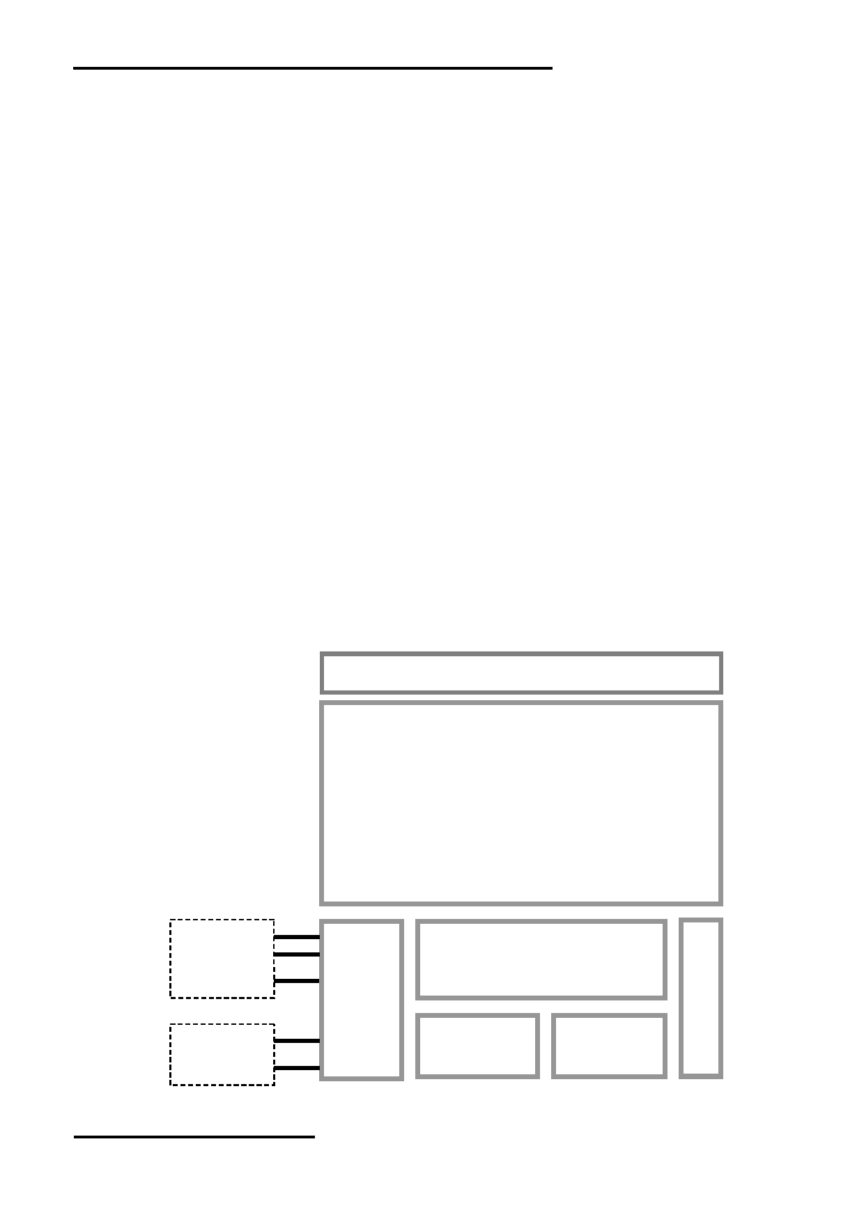
1.2 Block Diagram
Touch Panel
104” TFT
800 x 600 pixels
K8
RTS(BUSY)
TX, RX
Display Function Controller
VDD, VSS
with RTC
K6
ID, D-, D+
Flash
Memory
RAM
VUSB, VSS
URL: www.topwaydisplay.com
Document Name: HKT104ATA-C
Page: 3 of 10
TOPWAY
LCD Module User Manual
HKT104ATA-C
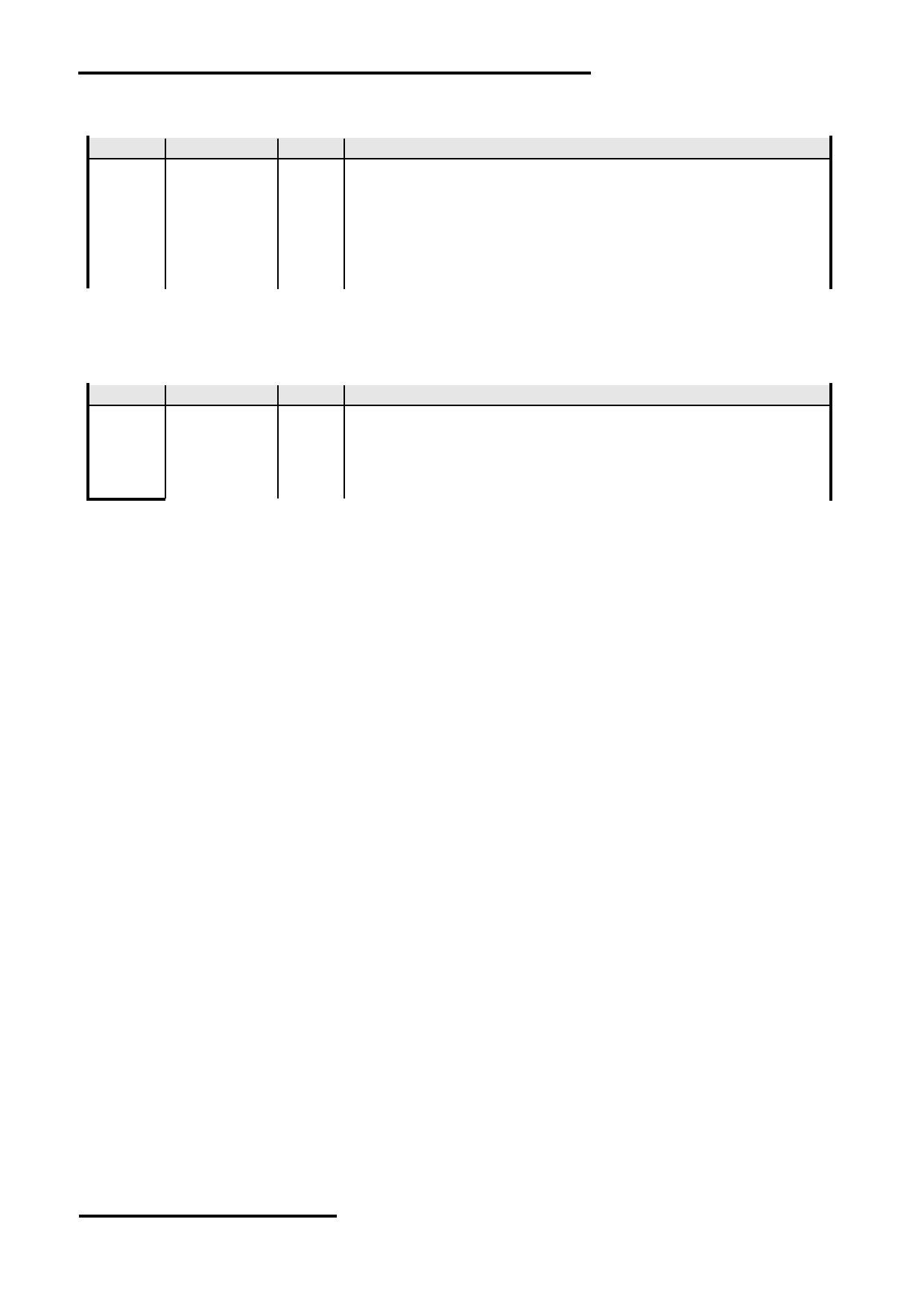
1.3 Terminal Function
RS232 Interface Terminal (K1)
Pin No.
Pin Name
I/O Descriptions
1
VDD
P
Power supply (6.0~26.0 V)
2
RX
I
Data Input
(eg. to PC’s RS-232C pin3 <9pin D-connector>)
3
TX
O
Data output
(eg. to PC’s RS-232C pin2 <9pin D-connector>)
4
RTS(BUSY)
O
Request To Send (could function as busy BUSY signal)
(eg. to PC’s RS-232C pin8 <9pin D-connector>)
5
NC
-
No Connection
6
VSS
P
Ground, (0V)
Note.
*1. User data and commands transfer through this terminal.
*2. HOST using command hand shake during communication is suggested.
USB Interface Terminal (K2)
Pin No.
Pin Name
I/O Descriptions
1
VUSB
P
Power supply(5.0 V)
2
D-
I/O
USB DATA negative signal
3
D+
I/O
USB DATA positive signal
4
ID
I
USB_ID,1:Client, 0:HOST
5
VSS
P
Ground, (0V)
Note.
*1. TML files and image files preload through this terminal
*2. Standard “USB-drive” functions provided
*3. During the files transfer, all others display functions will be suspended
URL: www.topwaydisplay.com
Document Name: HKT104ATA-C
Page: 4 of 10
TOPWAY
LCD Module User Manual
HKT104ATA-C
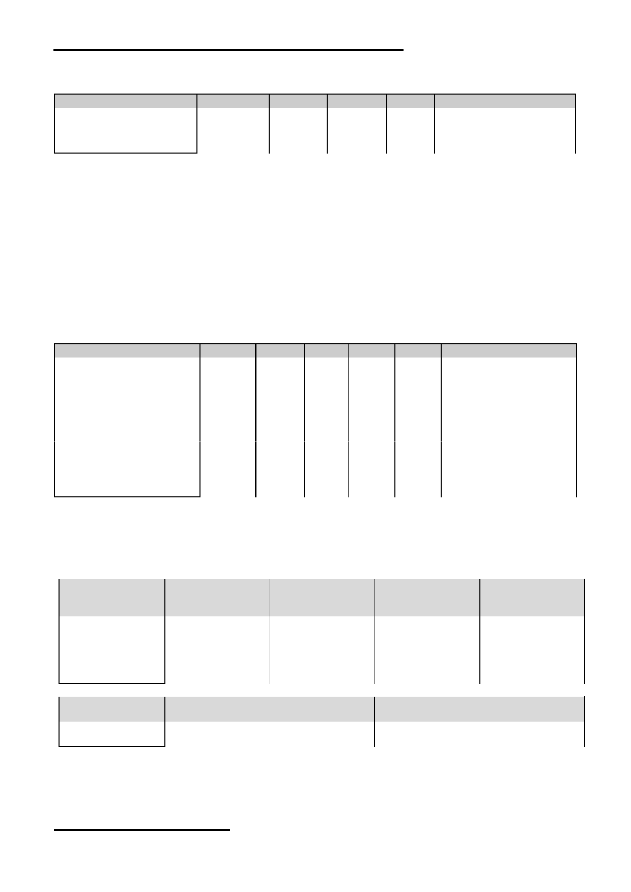
2 Absolute Maximum Ratings
Items
Symbol
Min.
Max.
Unit
Condition
Power Supply voltage
V DD
-0.3
26.0
V
Operating Temperature
T OP
-20
70
℃
No Condensation
Storage Temperature
T ST
-30
80
℃
No Condensation
Note:
*1. This rating applies to all parts of the module and should not be exceeded.
*2. The operating temperature only guarantees operation of the circuit. The contrast, response speed,
and the other specification related to electro-optical display quality is determined at the room temperature, T OP =25 ℃
*3. Ambient temperature when the backlight is lit (reference value)
*4. Any Stresses exceeding the Absolute Maximum Ratings may cause substantial damage to the device. Functional
operation of this device at other conditions beyond those listed in the specification is not implied and prolonged
exposure to extreme conditions may affect device reliability.
3 Electrical Characteristics
3.1 DC Characteristics
VSS=0V, VDD=12.0V,T OP =25 ℃
Items
Symbol
MIN.
TYP.
MAX.
Unit Applicable Pin/FUNC
Operating Voltage
V DD
6.0
12.0
26.0
V
VDD
RxD Input MARK(1)
V RxDM
-3.0
-
-15.0
V
RxD
RxD Input SPACE(0)
V RxDS
+3.0
-
+15.0
V
RxD
TxD Output MARK(1)
V TxDM
-3.0
-
-15.0
V
TxD
TxD Output SPACE(0)
V TxDS
+3.0
-
+15.0
V
TxD
RTS(BUSY) Output High
V TxDH
-3.0
-
-15.0
V
RTS(BUSY)
RTS(BUSY) Output Low
V TxDL
+3.0
-
+15.0
V
RTS(BUSY)
Operating Current
I DD
-
340
-
mA
VDD (*1)
Operating Current (USB)
I VUSB
-
150
-
mA
VUSB
Battery Supply Current
I BAT
-
6
-
uA
(*2)
Note.
*1. Normal display condition
*2. For Battery driving RTC application, RTC configuration should be enabled in the project global setting.
And after install/re-install the battery, it should be power-on once for correct RTC configurations
3.2 AC Characteristics
Items
JP1,JP7=close,
JP1,JP8=close,
JP1,JP8= open,
JP1,JP7= open,
JP2,JP8=open
JP2,JP7=open
JP2,JP7= close
JP2,JP8= close
(factory default)
Start bit
1
1
1
1
Data bit
8
8
8
8
Parity bit
None
None
Even
Odd
Stop bit
1
1
1
1
Baud Rate(*1)
115200 bps
9600 bps
115200 bps
115200 bps
Items
JP3=close, JP4=open
JP3= open, JP4=close
(factory default)
Serial Data
busy
Xon/Xoff
Flow Control
Note.
*1.Baud Rate (1200bps ~ 115200bps) could be adjusted by software.
URL: www.topwaydisplay.com
Document Name: HKT104ATA-C
Page: 5 of 10
TOPWAY
LCD Module User Manual
HKT104ATA-C
4 Function Specifications
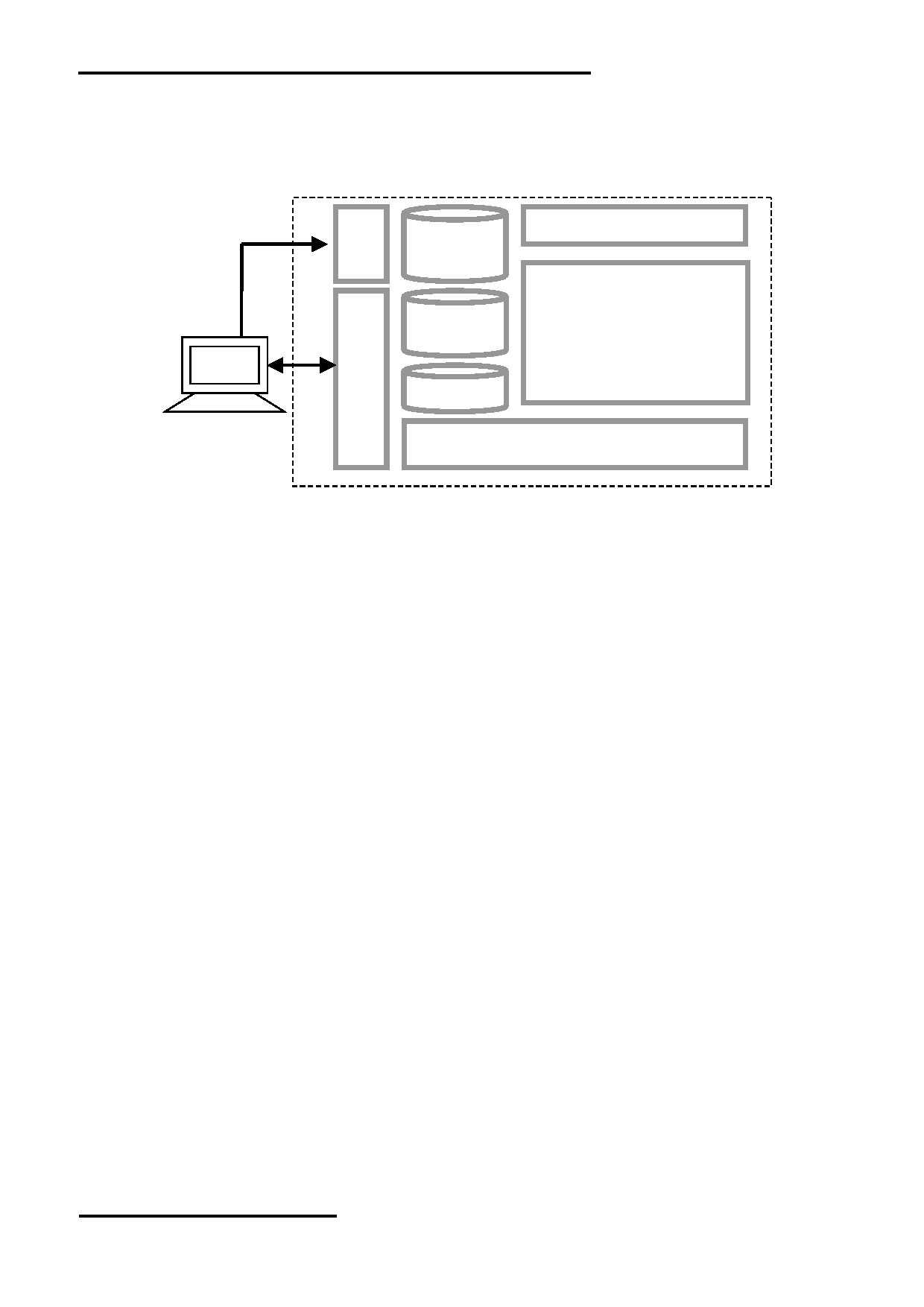
4.1 Basic Operation Function Descriptions
HKT104ATA-C
Touch Panel
TML files
Picture files
ICONS files
Custom
Memories
TFT Display
HOST
PC
VP variables
Control and Draw Engine
- TML files, Picture files, ICON files are stored inside FLASH memory area.
They are preloaded to HKT104ATA-C for stand alone interface use.
- Those files are preloaded via USB interface as an USB drive.
- All the interface flow and the touch response are based on the preloaded TML files
- VP variables memory is inside RAM area,
it provides real time access via UART by the HOST or display onto the TFT by TML file.
- Custom Memories are inside FLASH memory area
It can be accessed via UART interface by the HOST.
- Control and Draw Engine executes HOST commands and response respectively
- It also reports the real time Touch Key number to the HOST
URL: www.topwaydisplay.com
Document Name: HKT104ATA-C
Page: 6 of 10
TOPWAY
LCD Module User Manual
HKT104ATA-C
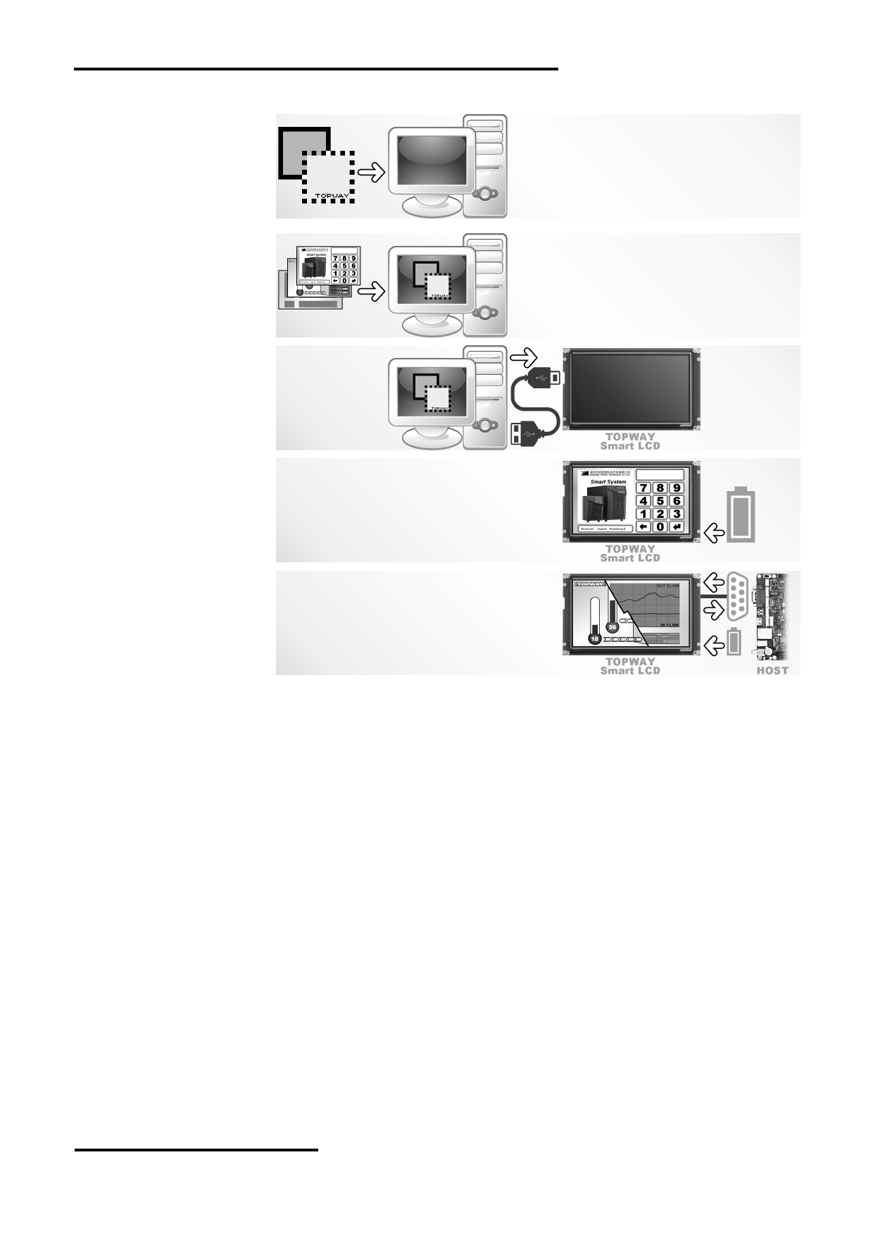
4.2 Quick Start Guide
1.
Install TOPWAY
Graphics Editor
Import pictures
2. design UI flow
3.
Download to
Smart LCD
4. power on &
display
Connect to
5.
host Show
real time
data
4.3 Command Descriptions
Please refer to “SMART LCD Command Manual” .
URL: www.topwaydisplay.com
Document Name: HKT104ATA-C
Page: 7 of 10
TOPWAY
LCD Module User Manual
HKT104ATA-C
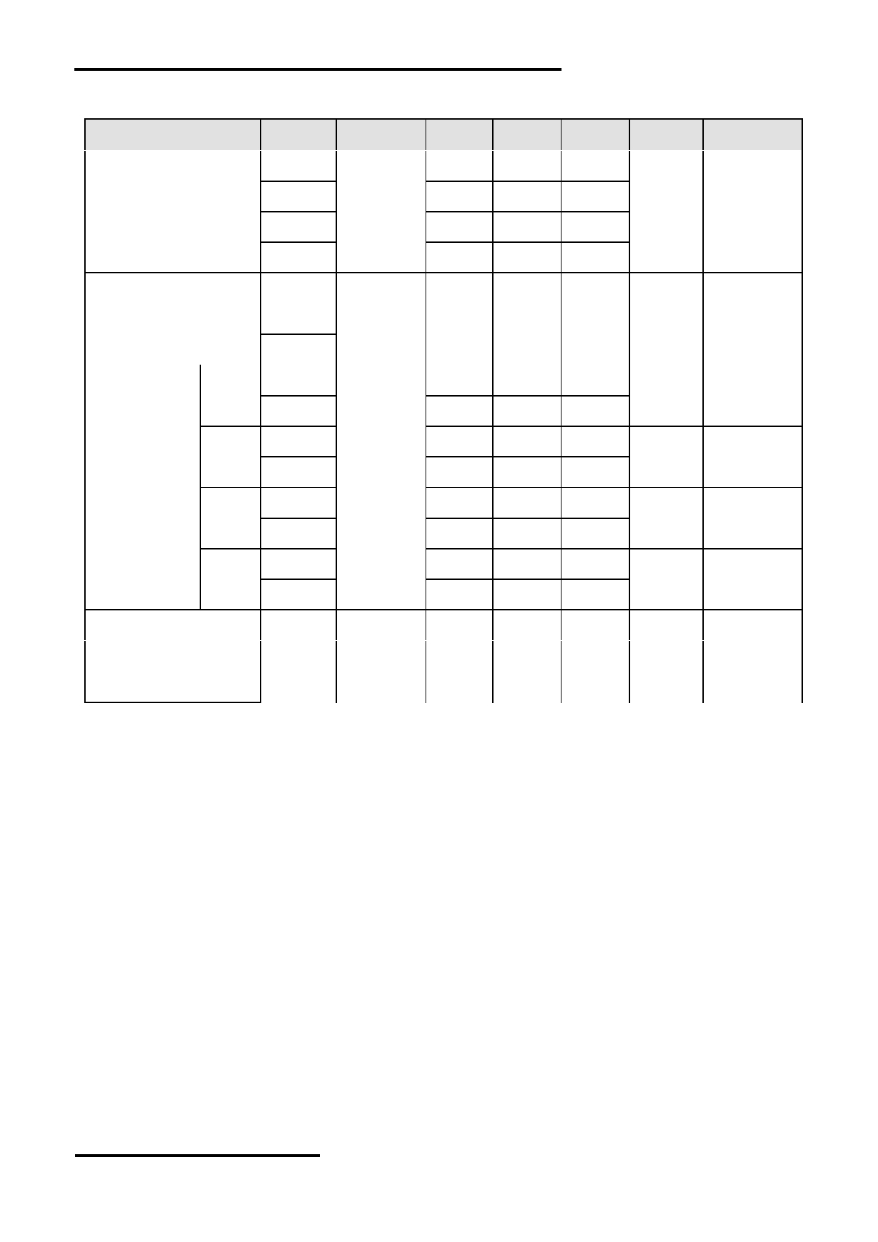
5 Optical Characteristics
Item
Symbol Condition
Min
Typ
Max
Unit
Remark
θT
70
80
-
View Angles
θB
CR ≧ 10
50
60
-
Degree Note2,3
θL
70
80
-
θR
70
80
-
Contrast Ratio
CR
θ=0°
700
900
-
Note 3
T ON
Response Time
25 ℃
-
20
30
ms
Note 4
T OFF
x
0.255
0.305
0.355
White
Note 1,5
y
0.277
0.327
0.377
x
0.534
0.584
0.634
Red
Note 1,5
Chromaticity
Backlight is
y
0.300
0.350
0.400
x
on
0.290
0.340
0.390
Green
Note 1,5
y
0.543
0.593
0.643
x
0.102
0.152
0.202
Blue
Note 1,5
y
0.040
0.090
0.140
Uniformity
U
75
80
-
%
Note 6
NTSC
45
50
-
%
Note 5
Luminance
L
-
250
-
cd/ ㎡
Note 7
1.IF= 40 mA, and the ambient temperature is 25 ℃ .
2. The test systems refer to Note 1 and Note 2.
URL: www.topwaydisplay.com
Document Name: HKT104ATA-C
Page: 8 of 10

TOPWAY
LCD Module User Manual
HKT104ATA-C
Note 1:
Note 2:
The data are measured after LEDs are turned on for 5 minutes.
The definition of viewing angle:
LCM displays full white. The brightness is the average value of 9 Refer to the graph below marked by θ and Ф
measured spots. Measurement equipment SR-3A (1°)
Measuring condition:
- Measuring surroundings: Dark room
- Measuring temperature: Ta=25 ℃ .
- Adjust operating voltage to get optimum contrast at
the center of the display.
Note 3:
The definition of contrast ratio (Test LCM using SR-3A (1°)):
Note 4:
Contrast
Luminance When LCD is at “White” state
Definition of Response time. (Test LCD using BM-7A(2°)):
Ratio(CR)
=
Luminance When LCD is at “Black” state
The output signals of photo detector are measured
(Contrast Ratio is measured in optimum common electrode
when the input signals are changed from
voltage)
“black” to “white”(falling time)
and from “white” to “black”(rising time), respectively.
The response time is defined as
the time interval between the 10% and 90% of amplitudes.Refer to
figure as below.
Note 5:
Note 6:
Definition of Color of CIE1931 Coordinate and NTSC Ratio.
The luminance uniformity is calculated by using following formula.
△ Bp = Bp (Min.) / Bp (Max.)×100 (%)
Color gamut:
Bp (Max.) = Maximum brightness in 9 measured spots
Area of RGB triangle
S=
X100%
Bp (Min.) = Minimum brightness in 9 measured spots .
Area of NTSC triangle
Note 7:
Measured the luminance of white state at center point
URL: www.topwaydisplay.com
Document Name: HKT104ATA-C
Page: 9 of 10
TOPWAY
LCD Module User Manual
HKT104ATA-C
6 Precautions of using LCD Modules
Please refer to "LCD-Module-Design-Handling-Precaution.pdf".
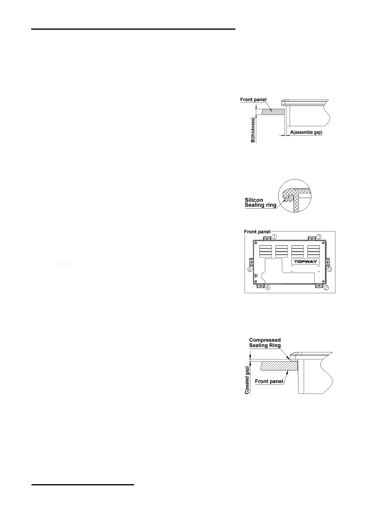
7 Assemble Precaution
安装注意事项
1. Customer front panel opening and thickness for TOPWAY
display module should be fit for its assembling and sealing.
The suggested assemble gap(A) should be about
0.3~0.5mm on each side.
The suggested front panel thickness(B) should be about
1.5~4.0mm.
客户面板开窗及厚度应适合 TOPWAY 显示模块的安装及密封 .
2. A silicon sealing ring ships with TOPWAY display module. It
should be in place before assembling to the front panel.
TOPWAY 显示模块上的硅胶密封圈在安装时确保嵌入到位 .
3. It should fix the TOPWAY display module into the front panel
with two steps.
Pre-fixing: Slightly tighten the screws on beam clamp in
sequence as picture on the right side.
Final-fixing: Tighten the fixing screws on beam clamp in
sequence as well with twist torque about 8~10kg.cm (*1) .
and put the beam clamp straight.
Note:
*1. Over tightening might damage the shell and cause bad sealing result.
应分两步将 TOPWAY 显示模块固定在面板上 .
意卡扣置正无歪斜 .
注 :
*1. 过度拧紧可能会损坏外壳和影响密封效果 .
4. It is strongly suggested to check the seal balancing of the
four-side of the TOPWAY display module.
The suggested after assemble sealed gap(C) should be
about 1.0~1.5mm.
需注意检查 TOPWAY 显示模块四周在安装后保证平衡密封 .
5. Others:
Never hot plug the device! Power off the device before connect or disconnect the display
module.
Don't forget to remove the cover protective film for normal operation.
其它 :
URL: www.topwaydisplay.com
Document Name: HKT104ATA-C
Page: 10 of 10