HMT050DTA-D
LCD Module User Manual
Prepared by:
Checked by:
Approved by:
Liusanyong
Date: 2018-11-15
Date:
Date:
Rev. Descriptions
Release Date
0.1
- Preliminary Draft release
2018-11-15
URL: www.topwaydisplay.com
Document Name: HMT050DTA-D
Page: 1 of 9

TOPWAY
LCD Module User Manual
HMT050DTA-D
Table of Content
1
Basic Specification ..................................................................................................................................... 3
1.1
General Specification ............................................................................................................................ 3
1.2
Block Diagram ...................................................................................................................................... 3
1.3
Terminal Function ................................................................................................................................. 4
2
Absolute Maximum Ratings....................................................................................................................... 4
3
Electrical Characteristics ........................................................................................................................... 5
3.1
DC Characteristics ................................................................................................................................ 5
4
Function Specifications ............................................................................................................................. 5
4.1
Basic Operation Function Descriptions ................................................................................................ 5
4.2
Quick Start Guide ................................................................................................................................. 6
4.3
Command Descriptions ........................................................................................................................ 6
5
Optical Characteristics ............................................................................................................................... 7
6
Precautions of using LCD Modules .......................................................................................................... 7
URL: www.topwaydisplay.com
Document Name: HMT050DTA-D
Page: 2 of 9
TOPWAY
LCD Module User Manual
HMT050DTA-D
1 Basic Specification
TOPWAY HMT050DTA-D is a Smart TFT Module with 32bit MCU on board. Its graphics engine provides
numbers of outstanding features. It supports TOPWAY TML for preload and pre-design display interface
that simplify the host operation and development time. Suitable for industry control, instrumentation,
medical electronics, power electric equipment applications.
1.1 General Specification
Screen Size(Diagonal) :
5.0”
Resolution :
800(RGB) x 480
Color Depth :
65k color (16bit)
Pixel Configuration :
RGB Stripe
Display Mode :
Transmissive / Normal White
Viewing Direction :
6H (*1) (gray-scale inverse)
12H (*2)
Outline Dimension :
143.5 x 81.0 x 14.7 (max) (mm)
(see attached drawing for details)
Active Area :
108.0 x 64.8 (mm)
Backlight :
LED
Command I/F:
RS-232C
Project Download:
by PC or by U-Drive (with OTG cable)
Operating Temperature :
-20 ~ +70°C
Storage Temperature :
-30 ~ +80°C
Note:
*1. For saturated color display content (eg. pure-red, pure-green, pure-blue, or pure-colors-combinations).
*2. For “color scales” display content.
*3. Color tone may slightly change by Temperature and Driving Condition.
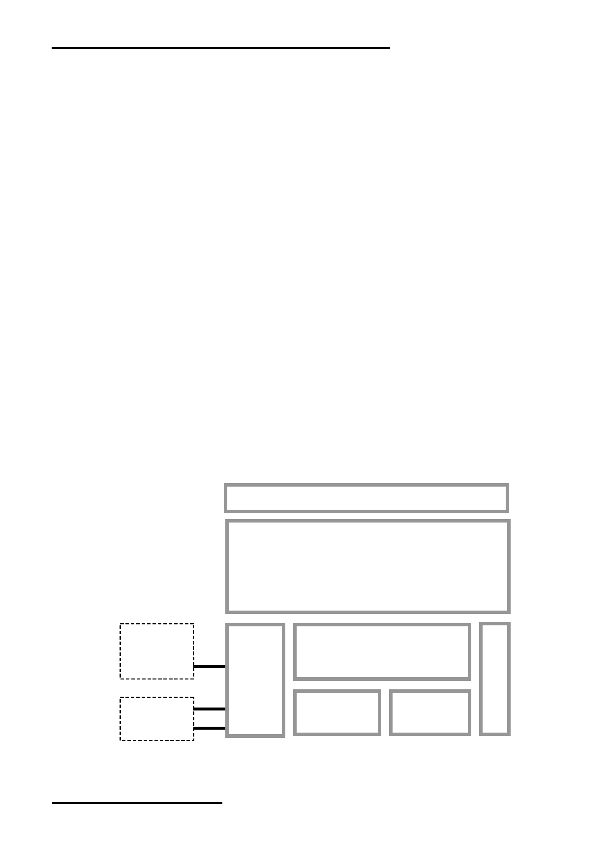
1.2 Block Diagram
Capacitive Touch Panel
5.0” TFT
800 x 480 pixels
K4
RTS(BUSY)
TX, RX
Display Function Controller
VDD, VSS
K3
ID, D-, D+
Flash
Memory
RAM
VUSB, VSS
URL: www.topwaydisplay.com
Document Name: HMT050DTA-D
Page: 3 of 9
TOPWAY
LCD Module User Manual
HMT050DTA-D
1.3 Terminal Function
RS232 Interface Terminal (K2/K4)
Pin No.
Pin Name
I/O Descriptions
1,2,3
VDD
P
Power supply (5.0V ~26.0 V)
4
NC
--
No connection, leave open
5
RX
I
Data Input (eg. to PC’s RS-232C pin3 <9pin D-connector>)
6
TX
O
Data output (eg. to PC’s RS-232C pin2 <9pin D-connector>)
7
RTS(BUSY)
O
Request To Send(could function as busy Busy signal)
(eg. to PC’s RS232C pin8 <9pin D-connector>)
8,9,10
VSS
P
Ground, (0V)
Note.
*1. User data and commands transfer through this terminal
*2. HW hand shake is suggested
USB Interface Terminal (K3)
Pin No.
Pin Name
I/O Descriptions
1
VUSB
P
Power supply(5.0V)
2
D-
I/O
USB DATA negative signal
3
D+
I/O
USB DATA positive signal
4
ID
I
USB_ID, 1:Client, 0:HOST
5
VSS
P
Ground, (0V)
Note.
*1. TML files and image files preload through this terminal
*2. Standard “USB-drive” functions provided
*3. During the files transfer, all others display functions will be suspended
2 Absolute Maximum Ratings
Items
Symbol
Min.
Max.
Unit
Condition
Power Supply voltage
V DD
-0.3
26.0
V
Operating Temperature
T OP
-20
70
℃
No Condensation
Storage Temperature
T ST
-30
80
℃
No Condensation
Note:
*1. This rating applies to all parts of the module and should not be exceeded.
*2. The operating temperature only guarantees operation of the circuit. The contrast, response speed,
and the other specification related to electro-optical display quality is determined at the room temperature, T OP =25 ℃
*3. Ambient temperature when the backlight is lit (reference value)
*4. Any Stresses exceeding the Absolute Maximum Ratings may cause substantial damage to the device. Functional
operation of this device at other conditions beyond those listed in the specification is not implied and prolonged
exposure to extreme conditions may affect device reliability.
URL: www.topwaydisplay.com
Document Name: HMT050DTA-D
Page: 4 of 9
TOPWAY
LCD Module User Manual
HMT050DTA-D
3 Electrical Characteristics
3.1 DC Characteristics
VSS=0V, VDD=12.0V, T OP =25 ℃
Items
Symbol
MIN.
TYP.
MAX.
Unit Applicable Pin/FUNC
Operating Voltage
V dd
5.0
12.0
26
V
VDD
RxD Input MARK(1)
V RxDM
-3.0
-
-15.0
V
Rx
RxD Input SPACE(0)
V RXDS
+3.0
-
+15.0
V
Rx
TxD Output MARK(1)
V TXDM
-3.0
-
-15.0
V
Tx
TxD Output SPACE(0)
V TXDS
+3.0
-
+15.0
V
Tx
RTS Output High
V TXDH
-3.0
-
-15.0
V
RTS(BUSY)
RTS Output Low
V TXDL
+3.0
-
+15.0
V
RTS(BUSY)
Operating Current
I DD
-
170
500
mA
VDD (*1)
Operating Current (USB)
I VUSB
-
170
250
mA
VUSB
Battery Supply Current
I BAT
-
0.6
-
uA
Note.
*1. Normal display condition
4 Function Specifications
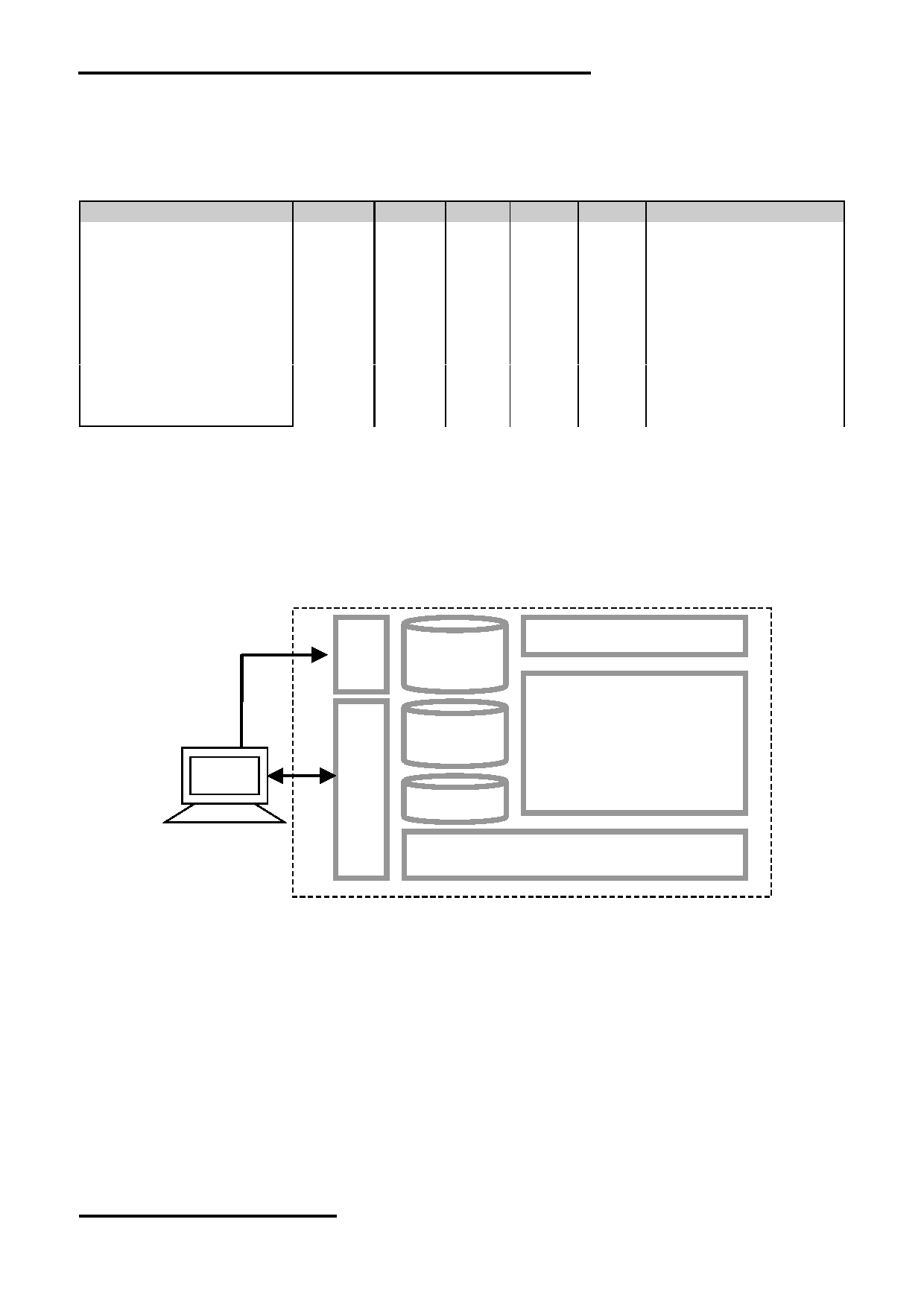
4.1 Basic Operation Function Descriptions
HMT050DTA-D
Capacitive Touch Panel
TML files
Picture files
ICONS files
Custom
Memories
TFT Display
HOST
PC
VP variables
Control and Draw Engine
- TML files, Picture files, ICON files are stored inside FLASH memory area.
They are preloaded to HMT050DTA-D for stand alone interface use.
- Those files are preloaded via USB interface as an USB drive.
- All the interface flow and the touch response are based on the preloaded TML files
- VP variables memory is inside RAM area,
it provides real time access via UART by the HOST or display onto the TFT by TML file.
- Custom Memories are inside FLASH memory area
It can be accessed via UART interface by the HOST.
- Control and Draw Engine executes HOST commands and response respectively
- It also reports the real time Touch Key number to the HOST
URL: www.topwaydisplay.com
Document Name: HMT050DTA-D
Page: 5 of 9
TOPWAY
LCD Module User Manual
HMT050DTA-D
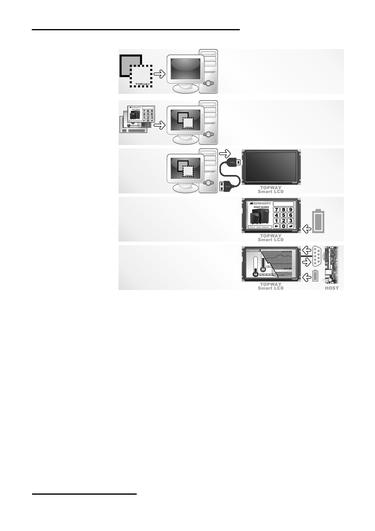
4.2 Quick Start Guide
1.
Install TOPWAY
Graphics Editor
Import pictures
2. design UI flow
3.
Download to
Smart LCD
4. power on &
display
Connect to
5.
host Show
real time
data
4.3 Command Descriptions
Please refer to “SMART LCD Command Manual”
URL: www.topwaydisplay.com
Document Name: HMT050DTA-D
Page: 6 of 9
TOPWAY
LCD Module User Manual
HMT050DTA-D
5 Optical Characteristics
Item
Symbol
Condition
MIN.
TYP.
MAX.
UNIT
Note.
θ L
9 o’clock
60
70
-
Viewing angle
θ R
3 o’clock
60
70
-
(CR ≥ 10)
degree
*2
θ T
12 o’clock
40
50
-
θ B
6 o’clock
60
70
-
T f
Response Time
25 ℃
-
20
30
ms
*3
T r
Contrast ratio
CR
500
600
-
-
W X
0.26
0.31
0.36
-
*1
Color chromaticity
Normal
W Y
θ=0 o
0.28
0.33
0.38
-
Luminance
L
-
200
-
cd/m 2
*4
Luminance uniformity
Y U
75
80
-
%
*4
Note:
*1. Definition of Contrast Ratio
The contrast ratio could be calculate by the following expression:
Contrast Ratio (CR) = Luminance with all pixels white / Luminance with all pixels black
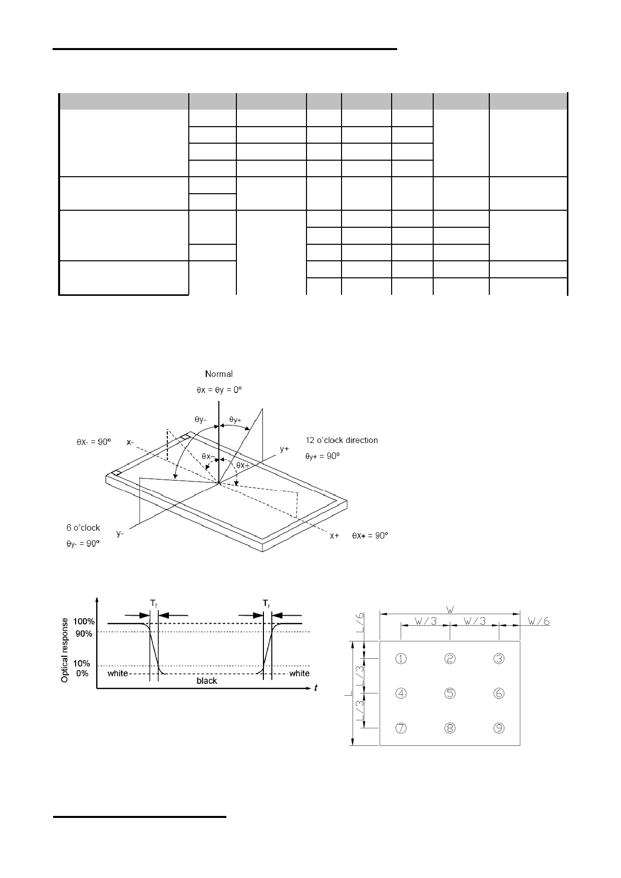
*2 Definition of Viewing Angle
*3 Definition of response time
*4 Definition of Luminance Uniformity
Luminance uniformity (Lu)=
Min. Luminance form pt1~pt9 / Max Luminance form Pt1~pt9
6 Precautions of using LCD Modules
Please refer to "LCD-Module-Design-Handling-Precaution.pdf".
URL: www.topwaydisplay.com
Document Name: HMT050DTA-D
Page: 7 of 9
TOPWAY
LCD Module User Manual
HMT050DTA-D
附录一:
CTP Application Precautions
1. CTP Mounting Precaution
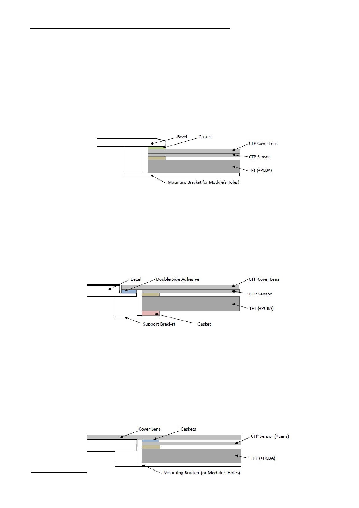
1.1 Bezel Mounting (Figure 1)
- The bezel window should be bigger than the CTP active area. It should be ≥ 0.5mm each side.
- Gasket should be installed between the bezel and the CTP surface.
The final gap should be about 0.5~1.0mm.
- It is recommended to provide an additional support bracket for backside support when
necessary (e.g. slim type TFT module without mounding structure). They should only provide
appropriate support and keep the module in place.
- The mounting structure should be strong enough to prevent external uneven force or twist act
onto the module.
Figure 1
1.2 Surface Mounting (Figure 2)
- As the CTP assembling on the countersink area with double side adhesive.
The countersink area should be flat and clean to ensure the double side adhesive installation
result.
- The Bezel is recommend to keep a gap ( ≥ 0.3mm each side) around the cover lens for tolerance.
- It is recommended to provide an additional support bracket with gasket for backside support
when necessary (e.g. TFT module without mounding structure). They should only provide
appropriate support and keep the module in place.
- The mounting structure should be strong enough to prevent external uneven force or twist act
onto the module.
Figure 2
1.3 Additional Cover Lens Mounting (Figure 3)
- For the case of additional cover Lens mounting, it is necessary to recheck with the CTP
specification about the material and thickness to ensure the functionality.
- It should keep a 0.2~0.3mm gap between the cover lens and the CTP surface..
- The cover lens window should be bigger than the active area of the CTP.
It should be ≥ 0.5mm each side.
- It is recommended to provide an additional support bracket for backside support when necessary
(e.g. slim type TFT module without mounding structure). They should only provide appropriate
support and keep the module in place.
- The mounting structure should be strong enough to prevent external uneven force or twist act
onto the module.
URL: www.topwaydisplay.com
Document Name: HMT050DTA-D
Page: 8 of 9

TOPWAY
LCD Module User Manual
HMT050DTA-D
Figure 3
2. Handling Precautions
2.1 The product made of glass. Do not subject it to a mechanical shock by dropping it from a high
place, etc.
2.2 Do not apply excessive or uneven force to the product since this may damage to the
performance.
2.3 If the display surface is contaminated, breathe on the surface and gently wipe it with a soft dry
cloth. If still not completely clear, moisten cloth with Isopropyl alcohol or Ethyl alcohol solvents.
Solvents other than those mentioned above may damage the product. Especially, do not use
Water, Ketone, Aromatic solvents.
2.4 Do not attempt to disassemble the CTP Module.
2.5 If the logic circuit power is off, do not apply the input signals.
2.6 To prevent destruction of the elements by static electricity, be careful to maintain an optimum
work environment.
a. Be sure to ground the body when handling the CTP Modules.
b. Tools required for assembly, such as soldering irons, must be properly ground.
c. To reduce the amount of static electricity generated, do not conduct assembly and other work
under dry conditions.
d. The CTP Module is coated with a film to protect the display surface. Be care when peeling off this
protective film since static electricity may be generated.
3. Storage and Transportation Precautions
3.1 When storing the CTP modules, avoid exposure to direct sunlight or to the light of fluorescent
lamps.
3.2 The CTP modules should be stored the required temperature range. If the CTP modules will be
stored for a long time, the recommend condition is the temperature of 0~40 ℃ and relative
humidity of ≤ 80%.
3.3 The LCD modules should be stored in the room without acid, alkali and harmful gas.
3.4 The CTP modules should be no falling and violent shocking during transportation, and also
should avoid excessive press, water, damp and sunshine.
URL: www.topwaydisplay.com
Document Name: HMT050DTA-D
Page: 9 of 9