LM3092ACW
LCD Module User Manual
Prepared by:
Checked by:
Approved by:
Wangxikuan
Date: 2017-08-15
Date:
Date:
Rev. Descriptions
Release Date
0.1
Preliminary New release
2017-07-24
0.2
Update Terminal Functions
2017-08-15
URL: www.topwaydisplay.com
Document Name: LM3092ACW-Manual-Rev0.2
Page: 1 of 10

TOPWAY
LCD Module User Manual
LM3092ACW
Table of Content
1. Basic Specifications .............................................................................................................. 3
1.1
Display Specifications ............................................................................................................................................ 3
1.2
Mechanical Specifications ...................................................................................................................................... 3
1.3
Block Diagram ........................................................................................................................................................ 3
1.4
Terminal Functions ................................................................................................................................................. 4
2. Absolute Maximum Ratings .................................................................................................. 5
3. Electrical Characteristics ...................................................................................................... 5
3.1
DC Characteristics ................................................................................................................................................. 5
3.2
LED Backlight Circuit Characteristics ..................................................................................................................... 5
3.3
AC Characteristics ................................................................................................................................................. 6
4. Function Specifications ......................................................................................................... 8
4.1
Adjusting the Display Contrast ............................................................................................................................... 8
4.2
Display Data RAM (DDRAM) ................................................................................................................................. 8
4.3
Display Commands ................................................................................................................................................ 9
5. Design and Handling Precaution ........................................................................................ 10
URL: www.topwaydisplay.com
Document Name: LM3092ACW-Manual-Rev0.2
Page: 2 of 10

TOPWAY
LCD Module User Manual
LM3092ACW
1. Basic Specifications
1.1 Display Specifications
1) LCD Display Mode
: FSTN, Positive, Transflective
2) Display Color
: Display Data = “1” : Dark Gray (*1)
: Display Data = “0” : Light Gray (*2)
3) Viewing Angle
: 6H
4) Driving Method
: 1/32 duty, 1/6bias
5) Back Light
: White LED backlight
Note:
*1. Color tone may slightly change by Temperature and Driving Condition
*2. The Color is defined as the inactive / background color
*3. Fine Contrast adjustment function is necessary in the application design for optimal display result
1.2 Mechanical Specifications
1) Outline Dimension
: 116.0 x 35.0 x 12.4MAX
(see attached Outline Drawing for details)
1.3 Block Diagram
URL: www.topwaydisplay.com
Document Name: LM3092ACW-Manual-Rev0.2
Page: 3 of 10
TOPWAY
LCD Module User Manual
LM3092ACW
1.4 Terminal Functions
Pin No.
Pin
Descriptions
K1&K2
Name
I/O
Serial mode <default>
Parallel mode
1
VSS
Power
Negative Power Supply, Ground (0V)
2
VDD
Power
Positive Power Supply
3
BLA
Positive Power Supply for
No Connection should leave
(NC)
Power
LED backlight
open
Chip Select
Register Select
CS=H,enable access to the
RS=H; Display data
4
CS
(RS)
Input
LCD module
RS=L; Control data
CS=L, disable access to
the LCD module
SID
Read write control
5
(R/W)
Input
Serial Data Input
R/W =H; data or status read
R/W =L; data or commmand
read
6
SCLK
(E)
Input
Serial Clock Input
Enable trigger
7
NC
(DB0)
I/O
data bus:
:
:
:
Connection to VSS,
Three state I/O terminal for
leave open
display data or instruction
14
NC
data
(DB7)
I/O
15
BLA
Power
Positive Power Supply for LED backlight
16
NC
No Connection should
Negative Power Supply for
(BLK)
-
leave open
LED backlight
Interface setting:
Setting
Interface
close
open
install
delete
3Line SPI
R7~R11=100R
mode(Default)
JP2,JP4~JP8
JP1,JP3
C1=C7=C8=0R
RP1,RP2,R1~R6
6800 mode
JP3,JP4
JP1,JP2,JP5~JP8 RP1,RP2,R1~R4
R5~R11
URL: www.topwaydisplay.com
Document Name: LM3092ACW-Manual-Rev0.2
Page: 4 of 10
TOPWAY
LCD Module User Manual
LM3092ACW
2. Absolute Maximum Ratings
Items
Symbol
Min.
Max.
Unit
Condition
Supply Voltage
V DD
-0.3
4.0
V
V SS = 0V
Input Voltage
V IN
-0.3
V DD +0.3
V
V SS = 0V
LCD Driving Voltage
V 0
-0.3
13.2
V
V SS = 0V
Operating Temperature
T OP
-20
+70
C
No Condensation
Storage Temperature
T ST
-30
+80
C
No Condensation
Cautions:
Any Stresses exceeding the Absolute Maximum Ratings may cause substantial damage to the device. Functional operation of this
device at other conditions beyond those listed in the specification is not implied and prolonged exposure to extreme conditions may
affect device reliability.
3. Electrical Characteristics
3.1 DC Characteristics
V SS =0V, V DD =3.3V, T OP =25 C
Items
Symbol
MIN.
TYP.
MAX.
Unit Applicable Pin
Operating Voltage
V DD
2.6
3.3
3.6
V
VDD
Input High Voltage
V IH1
0.9V DD
-
V DD
V
Input Low Voltage
V IL1
V SS
-
0.1V DD
V
RS,R/W,E,DB0~DB7
Operating Current
I DD
-
0.31
1.0
mA
VDD, VSS
3.2 LED Backlight Circuit Characteristics
V SS =0V, BLA=3.3V, T OP =25 C
Items
Symbol
MIN.
TYP.
MAX.
Unit
Applicable Pin
Forward Voltage
BLA
-
3.3
-
V
BLA
Forward Current
I BLA
-
37.5
100
mA
BLA
URL: www.topwaydisplay.com
Document Name: LM3092ACW-Manual-Rev0.2
Page: 5 of 10
TOPWAY
LCD Module User Manual
LM3092ACW
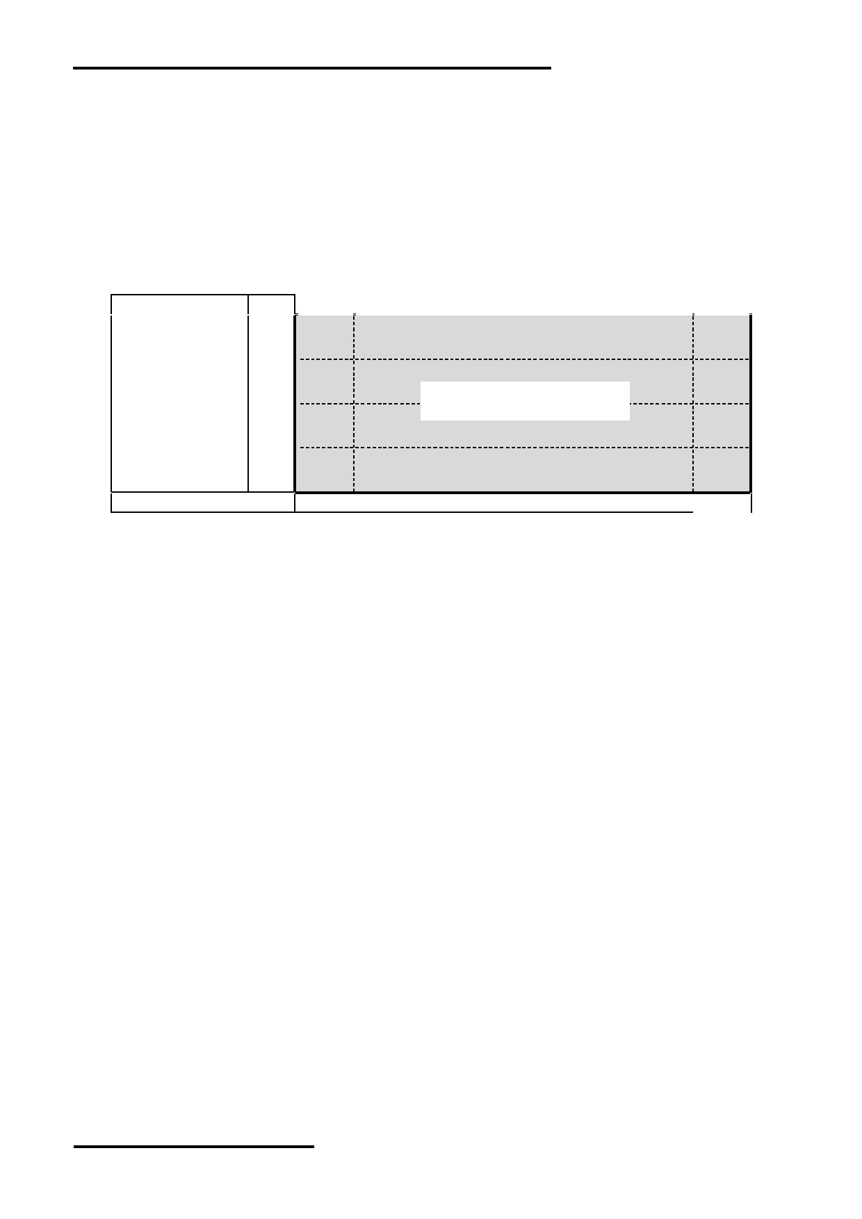
3.3 AC Characteristics
3.3.1 Serial Mode Interface( 3Line SPI mode )
V SS =0V, V DD =3.3V, T OP =25 C
Item
Symbol
MIN.
(Read/Write)
TYP.
MAX.
Unit
Clock cycle
tscyc
247/104
-
-
ns
CS setup time
tcss
13
ns
CS hold time
tcsh
13
ns
SCLK high pulse width
tshw
104/33
-
-
ns
SCLK low pulse width
tslw
104/33
-
-
ns
SCLK rise time
tr
-
-
15
ns
SCLK fall time
tf
-
-
15
ns
SID data setup time
tads
33
-
-
ns
SID data hold time
tadh
13
-
-
ns
Read access time
tacc
-
-
104
ns
Output disable time
tod
-
-
21
ns
Host Write Timing Diagram (Serial Mode)
URL: www.topwaydisplay.com
Document Name: LM3092ACW-Manual-Rev0.2
Page: 6 of 10
TOPWAY
LCD Module User Manual
LM3092ACW
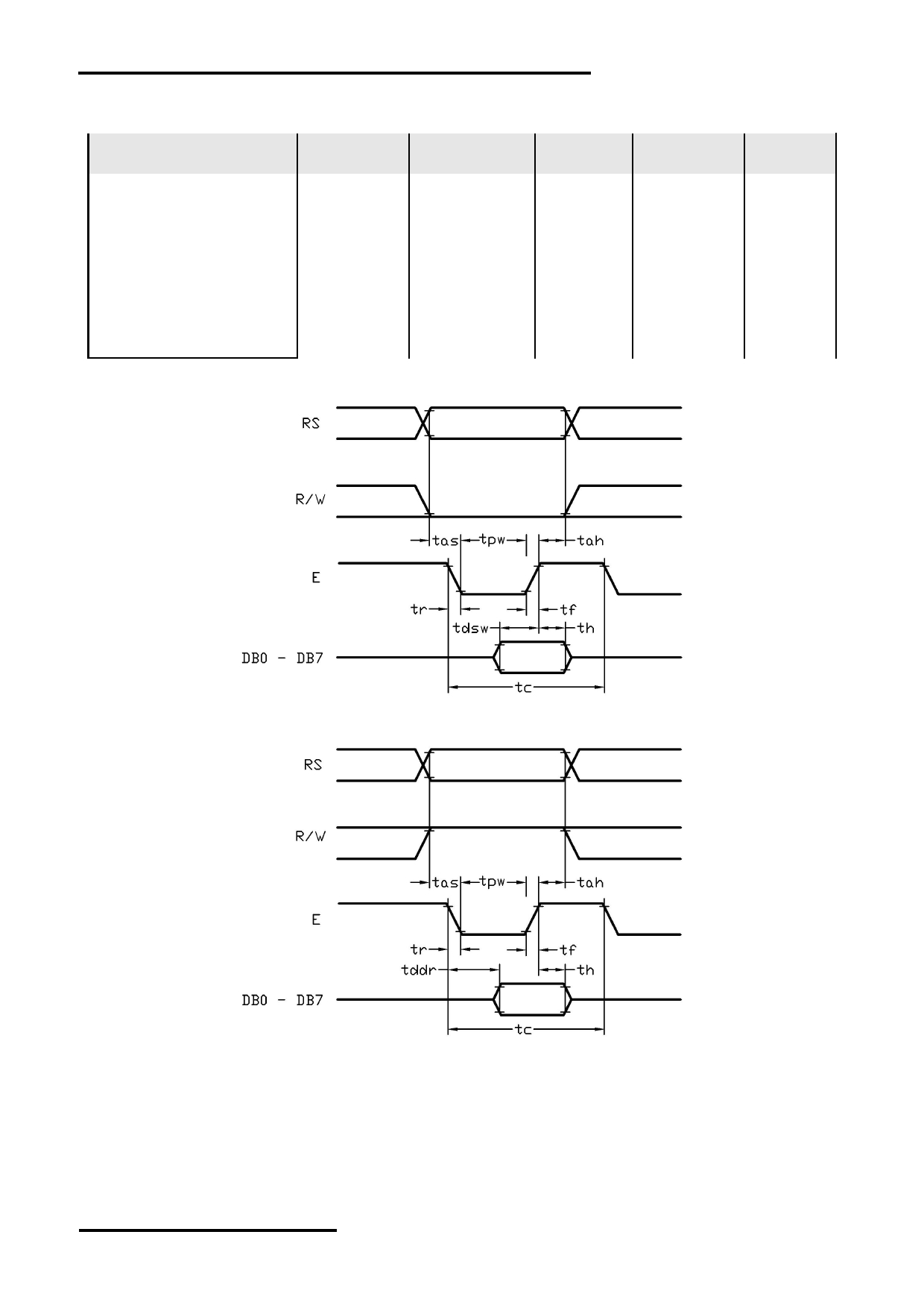
3.3.2 Parallel Mode Interface( 6800 mode )
V SS =0V, V DD =3.3V, T OP =25 C
Item
Symbol
MIN.
(Read/Write)
TYP.
MAX.
Unit
E cycle time
tc
221/143
-
-
ns
E high level width
tpw
91/52
-
-
ns
E rise time
tr
-
-
15
ns
E fall time
tf
-
-
15
ns
Address set-up time
tas
7
-
-
ns
Address hold time
tah
13
-
-
ns
Data set-up time
tdsw
46
-
-
ns
Data delay time
tddr
-
-
91
ns
Data hold time
th
-
-
28
ns
Host Write Timing Diagram (Parallel Mode)
Host Read Timing Diagram (Parallel Mode)
URL: www.topwaydisplay.com
Document Name: LM3092ACW-Manual-Rev0.2
Page: 7 of 10
TOPWAY
LCD Module User Manual
LM3092ACW
4. Function Specifications
4.1 Adjusting the Display Contrast
This LCD module equipped with latest digital contrast adjustment function.
Its display contrast could be adjusted by MCU command.
(Please see the command tables for details)
It is recommended to provide a contrast adjustment interface for end-user,
where the best display result could meet the individual preference in mass production.
4.2 Display Data RAM (DDRAM)
Page address
data
LCD Display (front view)
D0
0
:
D7
D0
1
:
D7
D0
2
:
160x32 pixels
D7
D0
3
:
D7
Column Address
10h
AFh
Note:
*1. DC(0) = 0 (normal)
*2. MX
= 0 (normal)
*3. MY
= 1 (mirror)
*4. Start Column Address = 0x10
URL: www.topwaydisplay.com
Document Name: LM3092ACW-Manual-Rev0.2
Page: 8 of 10

TOPWAY
LCD Module User Manual
LM3092ACW
4.3 Display Commands
Note:
*1. For the details of the Display Control Instructions, please refer to UC1609c series datasheet.
URL: www.topwaydisplay.com
Document Name: LM3092ACW-Manual-Rev0.2
Page: 9 of 10

TOPWAY
LCD Module User Manual
LM3092ACW
5. Design and Handling Precaution
Please refer to "LCD-Module-Design-Handling-Precaution.pdf".
URL: www.topwaydisplay.com
Document Name: LM3092ACW-Manual-Rev0.2
Page: 10 of 10