LM6093ACW
LCD Module User Manual
Prepared by:
Checked by:
Approved by:
Li KeKe
Date: 2020-05-14
Date:
Date:
Rev. Descriptions
Release Date
0.1
Prelimiay release
2020-05-14
URL: www.topwaydisplay.com
Document Name: LM6093ACW-Manual-Rev0.1.doc
Page: 1 of 14

TOPWAY
LCD Module User Manual
LM6093ACW
Table of Content
1. Basic Specifications...................................................................................................................3
1.1 Display Specifications ...................................................................................................................................................3
1.2 Mechanical Specifications..............................................................................................................................................3
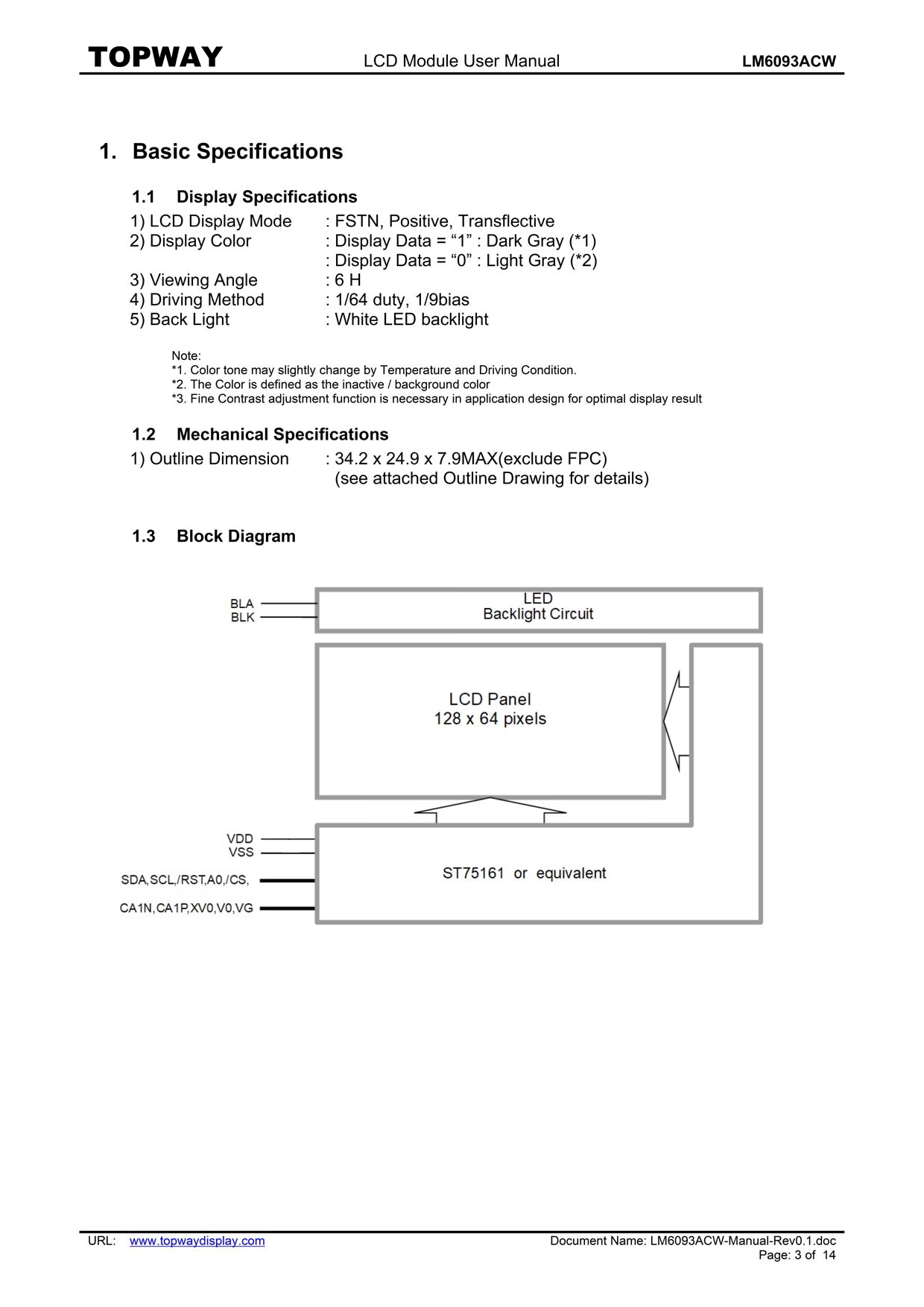
1.3 Block Diagram................................................................................................................................................................3
1.4 Terminal Functions.........................................................................................................................................................4
2. Absolute Maximum Ratings.......................................................................................................5
3. Electrical Characteristics...........................................................................................................5
3.1 DC Characteristics.........................................................................................................................................................5
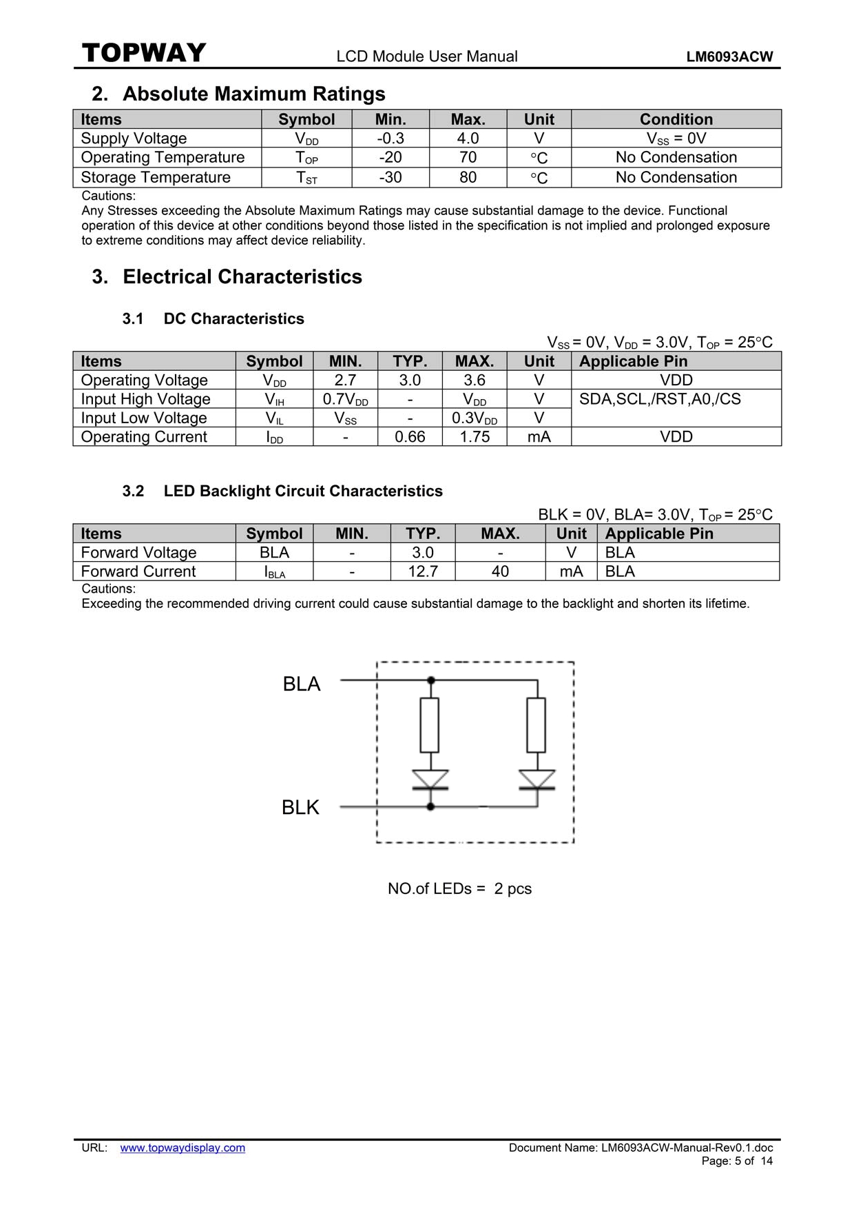
3.2 LED Backlight Circuit Characteristics.............................................................................................................................5
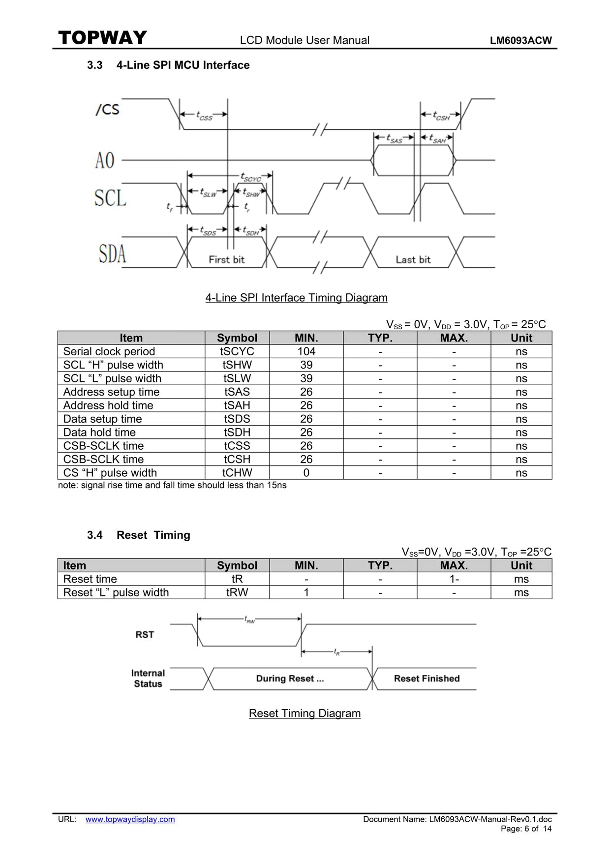
3.3 4-Line SPI MCU Interface..............................................................................................................................................6
3.4 Reset Timing .................................................................................................................................................................6
4. Function Specifications ............................................................................................................7
4.1 Application circuit(example)...........................................................................................................................................7
4.2 Adjusting the Display Contrast .....................................................................................................................................7
4.3 Resetting the LCD module.............................................................................................................................................7
4.4 Power off the LCD Module.............................................................................................................................................7
4.5 Refreshing The LCD Module..........................................................................................................................................7
4.6 Display Memory Map ...................................................................................................................................................8
4.7 Display Data RAM (DDRAM) .....................................................................................................................................9
4.8 Instructions ...............................................................................................................................................................10
Design and Handling Precaution ..............................................................................................14
URL: www.topwaydisplay.com
Document Name: LM6093ACW-Manual-Rev0.1.doc
Page: 2 of 14
TOPWAY
LCD Module User Manual
LM6093ACW
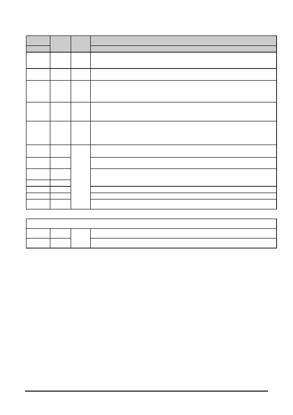
1.4 Terminal Functions
Pin No.
Pin
I/O
Descriptions
K1
Name
4-Line SPI
1
SDA
I
SDA_IN, serial input data.
2
SCL
I
serial input clock (SCL).
Reset signal.
3
/RST
I
/RST = L, internal Initialization is executed.
/RST = H, Normal running.
Register Select
4
A0
I
A0 = H, Transferring the Display RAM data.
A0 = L, Transferring the Instruction data.
Chip select input pin.
5
/CS
I
/CS=“L”: This chip is selected and the MPU interface is active.
/CS=“H”: This chip is not selected and the MPU interface is disabled .
6
VSS
Negative Power Supply, Ground (0V)
7
VDD
Positive Power Supply.
8
CA1N
Power DC/DC voltage converter. Connect a capacitor between CA1P and CA1N.
9
CA1P
10
XV0
Negative operating voltage of COM-drivers.
11
V0
Positive operating voltage of COM-drivers.
12
VG
VG is the power of SEG-drivers.
LED Backlight
1
BLA
Positive Power Supply.
Power
2
BLK
Negative Power Supply, Ground (0V).
URL: www.topwaydisplay.com
Document Name: LM6093ACW-Manual-Rev0.1.doc
Page: 4 of 14
TOPWAY
LCD Module User Manual
LM6093ACW
4. Function Specifications
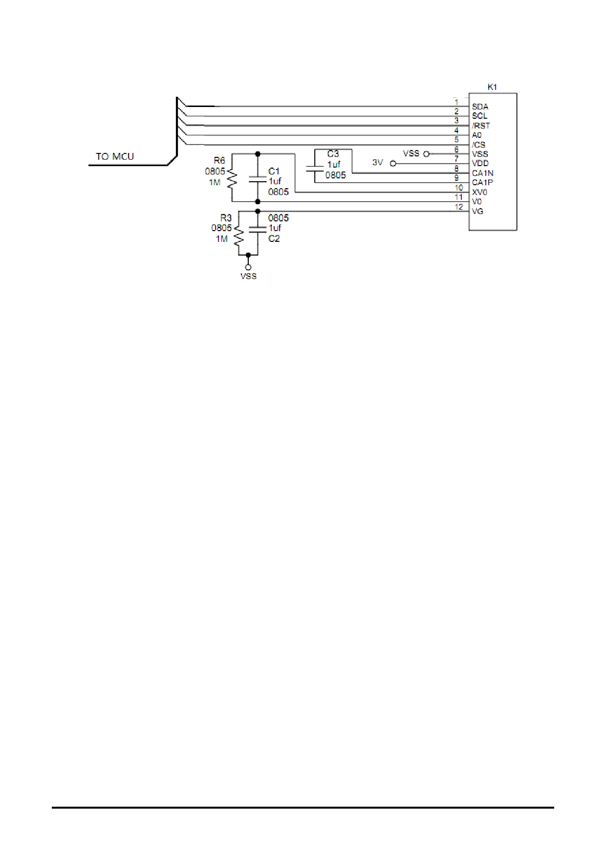
4.1 Application circuit(example)
4.2
Adjusting the Display Contrast
-- This LCD module equipped with latest digital contrast adjustment function.
-- Its display contrast could be adjusted by MCU command. (Please see the command tables
for details)
-- It is recommended to provide a contrast adjustment interface for end-user, where the best
display result could meet the individual preference in mass production.
4.3 Resetting the LCD module
The LCD module should be initialized by setting /RST terminal at low level after the power supply
stable.
4.4 Power off the LCD Module
It recommends that LCD module should enter sleep mode before power off.
4.5 Refreshing The LCD Module
It recommends that the operating modes and display contents should be refreshed periodically to
prevent the effect of unexpected noise.
URL: www.topwaydisplay.com
Document Name: LM6093ACW-Manual-Rev0.1.doc
Page: 7 of 14
TOPWAY
LCD Module User Manual
LM6093ACW
4.6 Display Memory Map
Page
Address
Data
LCD Module Top View
D7
0
:
D0
D7
1
:
D0
:
:
D7
5
:
128x64 pixels
D0
:
:
D7
7
:
D0
Column Address
00H
7Fh
Internal Display RAM Address
Note: Display start line = 0,INV = 0.
URL: www.topwaydisplay.com
Document Name: LM6093ACW-Manual-Rev0.1.doc
Page: 8 of 14

TOPWAY
LCD Module User Manual
LM6093ACW
4.7 Display Data RAM (DDRAM)
URL: www.topwaydisplay.com
Document Name: LM6093ACW-Manual-Rev0.1.doc
Page: 9 of 14
TOPWAY
LCD Module User Manual
LM6093ACW
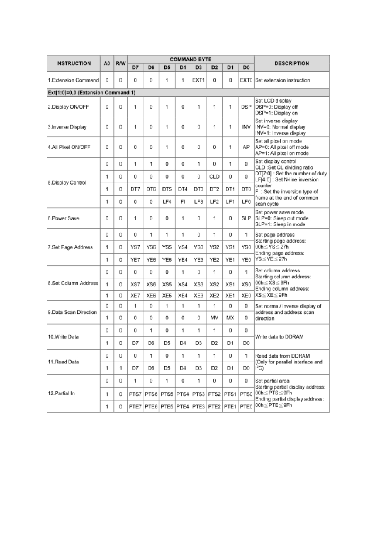
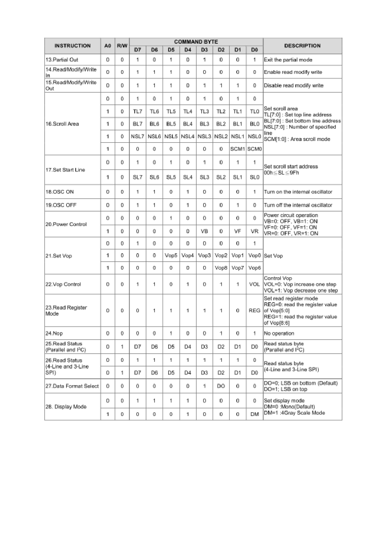
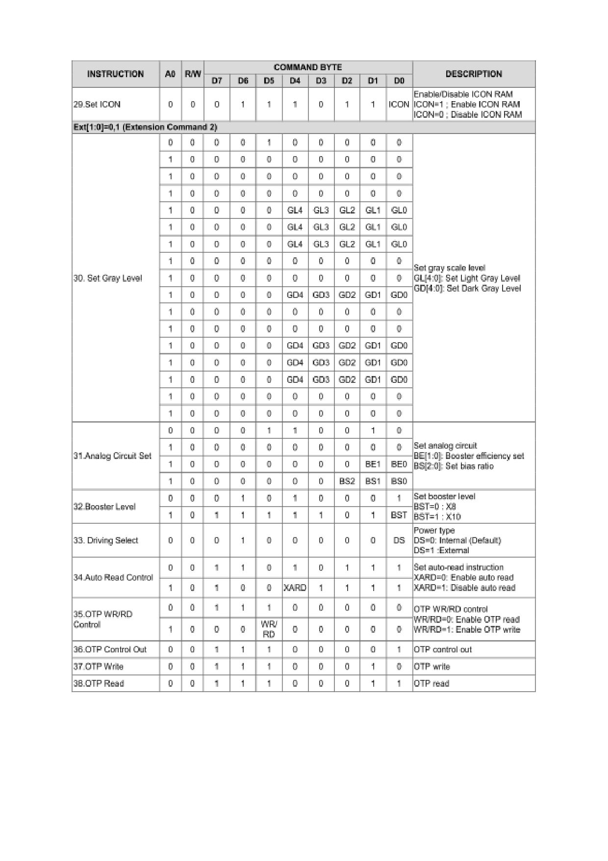
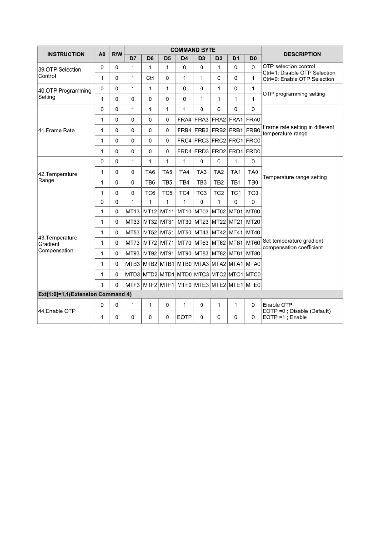
4.8 Instructions
URL: www.topwaydisplay.com
Document Name: LM6093ACW-Manual-Rev0.1.doc
Page: 10 of 14
TOPWAY
LCD Module User Manual
LM6093ACW
URL: www.topwaydisplay.com
Document Name: LM6093ACW-Manual-Rev0.1.doc
Page: 11 of 14
TOPWAY
LCD Module User Manual
LM6093ACW
URL: www.topwaydisplay.com
Document Name: LM6093ACW-Manual-Rev0.1.doc
Page: 12 of 14
TOPWAY
LCD Module User Manual
LM6093ACW
Note:
*1. Do not use any other command not listed, or the system malfunction may result.
*2. For the details of the Display Commands, please refer to ST75161 data sheet.
URL: www.topwaydisplay.com
Document Name: LM6093ACW-Manual-Rev0.1.doc
Page: 13 of 14

TOPWAY
LCD Module User Manual
LM6093ACW
Design and Handling Precaution
1.
The LCD panel is made by glass. Any mechanical shock (eg. dropping form high place)
will damage the LCD module.
2.
Do not add excessive force on the surface of the display, which may cause the Display
color change abnormally.
3.
The polarizer on the LCD is easily get scratched. If possible, do not remove the LCD
protective film until the last step of installation.
4.
Never attempt to disassemble or rework the LCD module.
5.
Only Clean the LCD with Isopropyl Alcohol or Ethyl Alcohol. Other solvents (eg. water)
may damage the LCD.
6.
When mounting the LCD module, make sure that it is free form twisting, warping and
distortion.
7.
Ensure to provide enough space (with cushion) between case and LCD panel to
prevent external force adding on it, or it may cause damage to the LCD or degrade the
display result.
8.
Only hold the LCD module by its side. Never hold LCD module by add force on the heat
seal or TAB.
9.
Never add force to component of the LCD module. It may cause invisible damage or
degrade of the reliability.
10.
LCD module could be easily damaged by static electricity. Be careful to maintain an
optimum anti-static work environment to protect the LCD module.
11.
When peeling off the protective film from LCD, static charge may cause abnormal
display pattern. It is normal and will resume to normal in a short while.
12.
Take care and prevent get hurt by the LCD panel sharp edge.
13.
Never operate the LCD module exceed the absolute maximum ratings.
14.
Keep the signal line as short as possible to prevent noisy signal applying to LCD
module.
15.
Never apply signal to the LCD module without power supply.
16.
IC chip (eg. TAB or COG) is sensitive to the light. Strong lighting environment could
possibly cause malfunction. Light sealing structure casing is recommend.
17.
LCD module reliability may be reduced by temperature shock.
18.
When storing the LCD module, avoid exposure to the direct sunlight, high humidity, high
temperature or low temperature. They may damage or degrade the LCD module
URL: www.topwaydisplay.com
Document Name: LM6093ACW-Manual-Rev0.1.doc
Page: 14 of 14