LMK104DNEFWU-AKA
LCD Module User Manual
Prepared by:
Checked by:
Approved by:
LU JIANHUI
Date: 2017-05-02
Date:
Date:
Rev. Descriptions
Release Date
0.1
New release
2017-05-02
NURL: www.topwaydisplay.com
Document Name: LMK104DNEFWU-AKA-Manual-Rev0.1
Page: 1 of 10

TOPWAY
LCD Module User Manual
LMK104DNEFWU-AKA
Table of Content
1. General Specification ............................................................................................................ 3
2. Block Diagram ........................................................................................................................ 3
3. Terminal Function .................................................................................................................. 4
3.1
K1 Terminal(DVI Right angle connector) ................................................................................................................ 4
4. Absolute Maximum Ratings .................................................................................................. 4
5. Electrical Characteristics ...................................................................................................... 5
5.1
DC Characteristics ................................................................................................................................................. 5
5.2
DC Characteristics(LVDS) ..................................................................................................................................... 5
5.3
POWER ON/OFF SEQUENCE .............................................................................................................................. 5
6. AC Characteristics ................................................................................................................. 6
6.1
AC Characteristics(LVDS) ...................................................................................................................................... 6
6.2
AC Characteristics(TFT) ........................................................................................................................................ 8
7. Optical Characteristics .......................................................................................................... 9
8. Precautions for Use of LCD Modules ................................................................................. 10
8.1
Handling Precautions ................................................................................................................. 错误 ! 未定义书签。
8.2
Storage precautions ................................................................................................................... 错误 ! 未定义书签。
8.3
Transportation Precautions ........................................................................................................ 错误 ! 未定义书签。
NURL: www.topwaydisplay.com
Document Name: LMK104DNEFWU-AKA-Manual-Rev0.1
Page: 2 of 10
TOPWAY
LCD Module User Manual
LMK104DNEFWU-AKA
1. General Specification
Signal Interface :
LVDS (JEIDA 24 bits)
Display Mode :
Transmissive with Normally White
Screen Size :
10.4 inch
Outline Dimension :
272.0x 214.0 x 35.0(mm)
(see outline drawing for details)
Active Area :
211.20x 158.40(mm)
Number of dots :
800x 3 (RGB) x 600
Dot Pitch :
0.264x0.264 (mm)
Pixel Configuration :
R.G.B. Vertical Stripe
Backlight :
White LED
Viewing Direction :
12 o’clock (*1)
6 o’clock ( Gray scale Inversion ) (*2)
Operating Temperature :
-20 ~ +70°C
Storage Temperature :
-30 ~ +80°C
Note:
*1. For “ color scales ” display content.
*2. For saturated color display content (eg. pure-red, pure-green, pure-blue or pure-colors -combinations).
*3. Color tone may slightly change by temperature and driving condition.
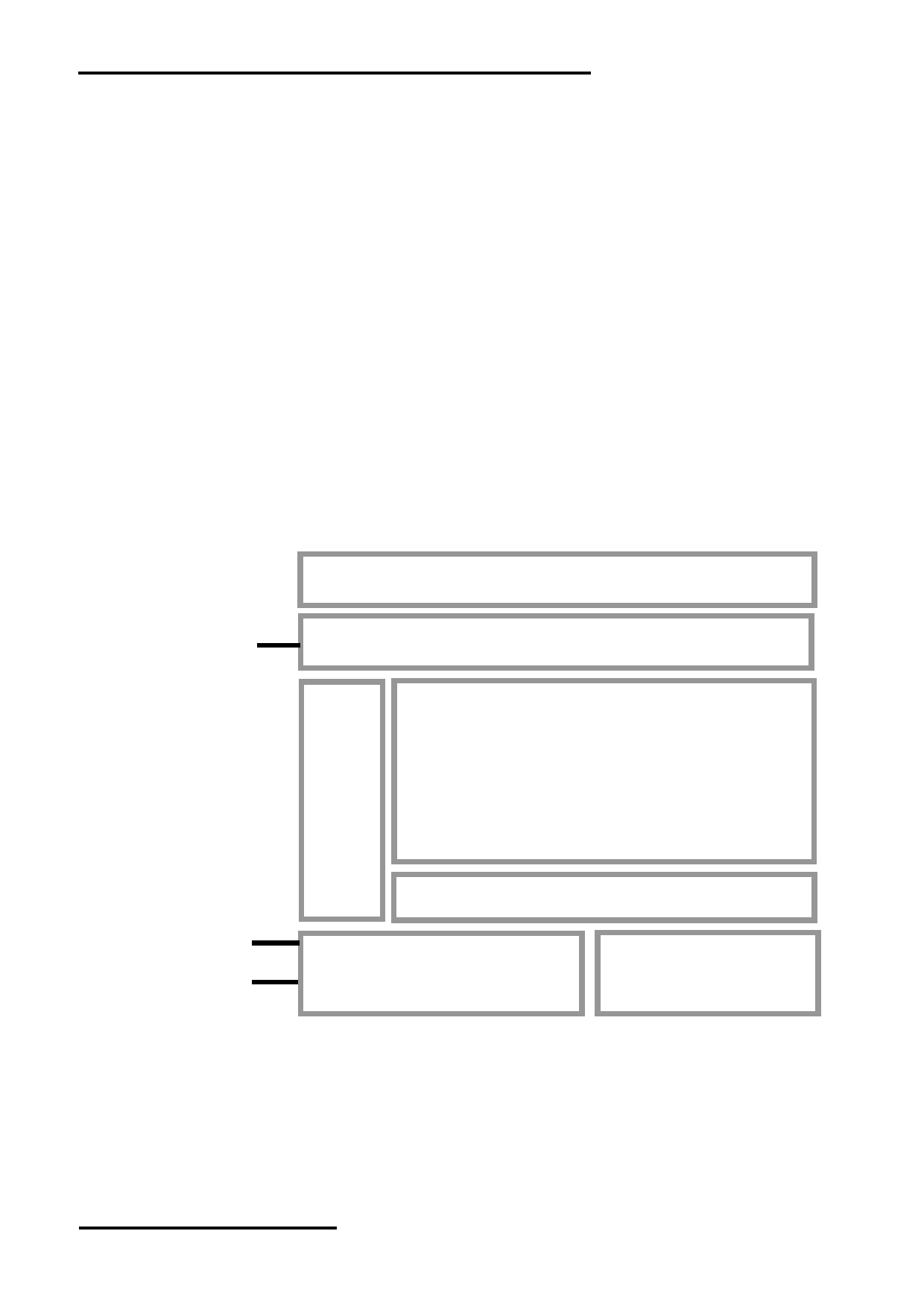
2. Block Diagram
BL_PWM
Backlight Circuit
Touch Panel
USB_DM, USB_DP
800(x3) x 600 pixels
Source Driver
VDD,GND
RX0+,RX0-,RX1+,RX1-
LVDS interface
Power Circuit
RX2+,RX2-,RX3+,RX3-
RxCLK+,RxCLK-
NURL: www.topwaydisplay.com
Document Name: LMK104DNEFWU-AKA-Manual-Rev0.1
Page: 3 of 10
TOPWAY
LCD Module User Manual
LMK104DNEFWU-AKA
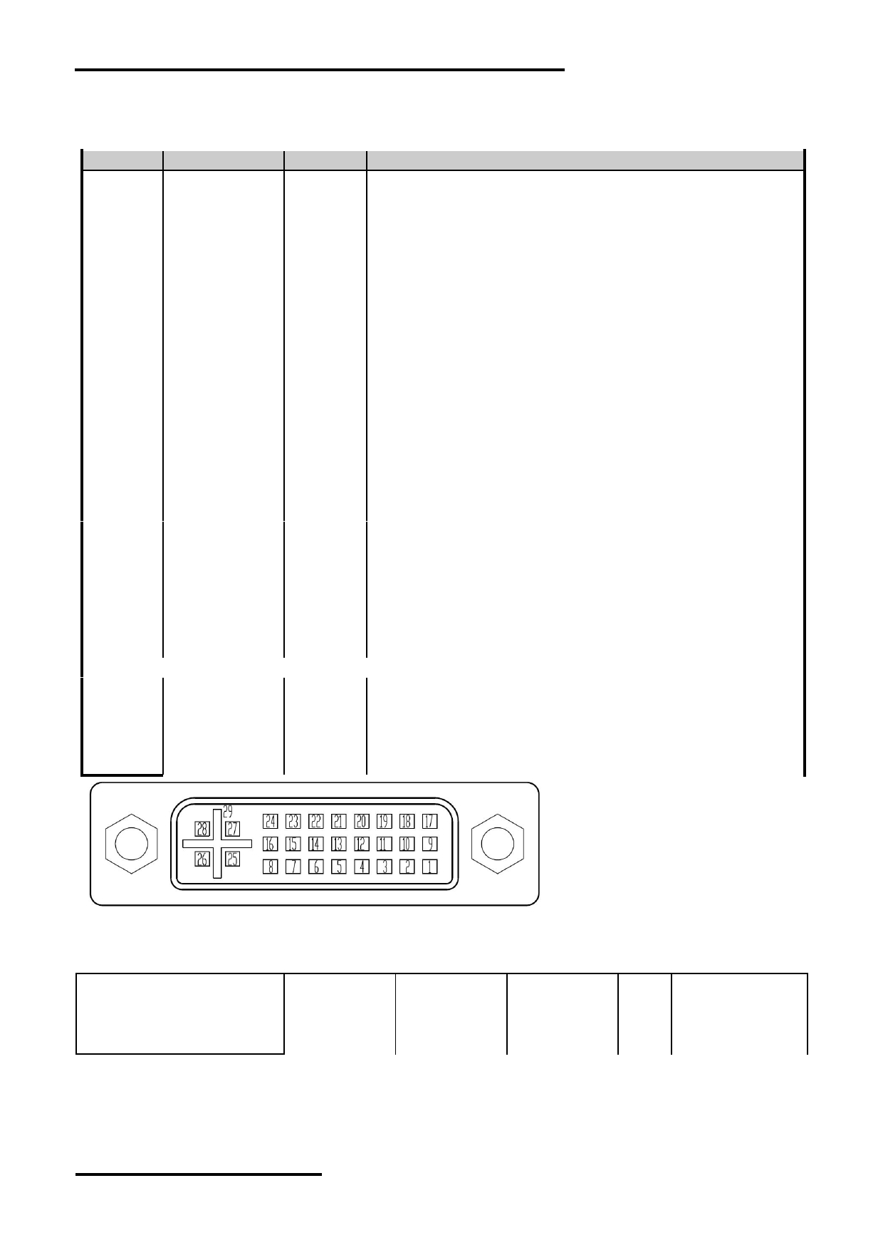
3. Terminal Function
3.1 K1 Terminal(DVI Right angle connector)
Pin No.
Pin Name
IO
Descriptions
1
RX2-
Input
LVDS receiver negative signal channel 2
2
RX2+
Input
LVDS receiver positive signal channel 2
3
GND
Power Ground
4
BL_PWM
Input
Backlight dimming control(High actives)
PWM may be used to adjust the output brightness
5
NC
-
No connection
6
VDD
Power Positive Power Supply(5.0V)
7
VDD
Power Positive Power Supply(5.0V)
8
VDD
Power Positive Power Supply(5.0V)
9
RX1-
Input
LVDS receiver negative signal channel 1
10
RX1+
Input
LVDS receiver positive signal channel 1
11
GND
Power Ground
12
RX3-
Input
LVDS receiver negative signal channel 3
13
RX3+
Input
LVDS receiver positive signal channel 3
14
VDD
Power Positive Power Supply(5.0V)
15
GND
Power Ground
16
GND
Power Ground
17
RX0-
Input
LVDS receiver negative signal channel 0
18
RX0+
Input
LVDS receiver positive signal channel 0
19
GND
Power Ground
20
USB_DM
I/O
USB D- signal
21
USB_DP
I/O
USB D+ signal
22
GND
Power Ground
23
RXCLK+
Input
LVDS receiver positive signal clock
24
RXCLK-
Input
LVDS receiver negative signal clock
25
VDD
Power Positive Power Supply(5.0V)
26
VDD
Power Positive Power Supply(5.0V)
27
NC
-
No connection
28
NC
-
No connection
29
GND
Power Ground
4. Absolute Maximum Ratings
Items
Symbol
Min.
Max.
Unit Condition
Power Supply voltage
VDD
-0.3
5.5
V
Operating Temperature
T OP
-20
70
C
No Condensation
Storage Temperature
T ST
-30
80
C
No Condensation
Note:
*1. This rating applies to all parts of the module. And should not be exceeded.
*2. The operating temperature only guarantees operation of the circuit. The contrast, response speed,
and the other specification related to electro-optical display quality is determined at the room temperature, T OP =25 ℃
*3. Any Stresses exceeding the Absolute Maximum Ratings may cause substantial damage to the device. Functional
operation of this device at other conditions beyond those listed in the specification is not implied and prolonged
exposure to extreme conditions may affect device reliability.
NURL: www.topwaydisplay.com
Document Name: LMK104DNEFWU-AKA-Manual-Rev0.1
Page: 4 of 10
TOPWAY
LCD Module User Manual
LMK104DNEFWU-AKA
5. Electrical Characteristics
5.1 DC Characteristics
VDD=5.0V,GND=0V,T a =25 C
Items
Symbol
MIN.
TYP.
MAX.
Unit
Note
Supply Voltage
VDD
4.7
5.0
5.3
V
VDD Power Consumption
I dd
--
0.79
1.58
A
*1
Input High Voltage
V IH
3.0
3.3
-
V
BL_PWM
Input Low Voltage
V IL
GND
-
0.3
V
BL_PWM
Note1:
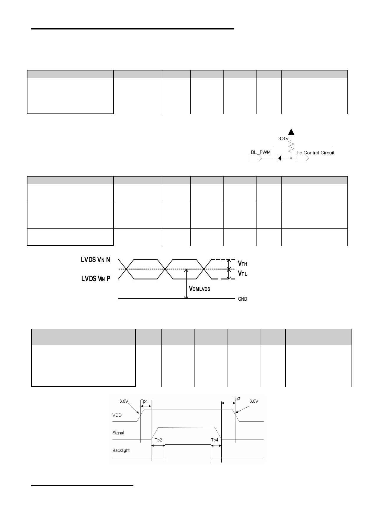
*1. BL_PWM=Hi;
*3. Terminal circuit.
*2. Recommended BL_ PWM PWM Freq. is 3kHz.
5.2 DC Characteristics(LVDS)
VDD=5.0V,GND=0V,T a =25 C
Items
Symbol
MIN.
TYP.
MAX.
Unit
Note
Differential Input High
Threshold
V TH
-
-
100
mV
Differential Input Low
Threshold
V TL
-100
-
-
mV
Input Current
I IN
± 10
uA
Differential Input common
Mode voltage
V CMLVDS
1.65
-
2.1
V
LVDS DC timing diagram
5.3 POWER ON/OFF SEQUENCE
Parameter
Symb
MIN.
TYP.
MAX.
Unit Note
ol
VDD from3.0V to signal starting
Tp1
0
-
50
ms
Signal staring to backlight on
Tp2
150
-
-
ms
Signal off to VDD reach 3.0V
Tp3
0
-
50
ms
Backlight off to signal off
Tp4
150
-
-
ms
Interface Power On/Off Sequence
NURL: www.topwaydisplay.com
Document Name: LMK104DNEFWU-AKA-Manual-Rev0.1
Page: 5 of 10
TOPWAY
LCD Module User Manual
LMK104DNEFWU-AKA
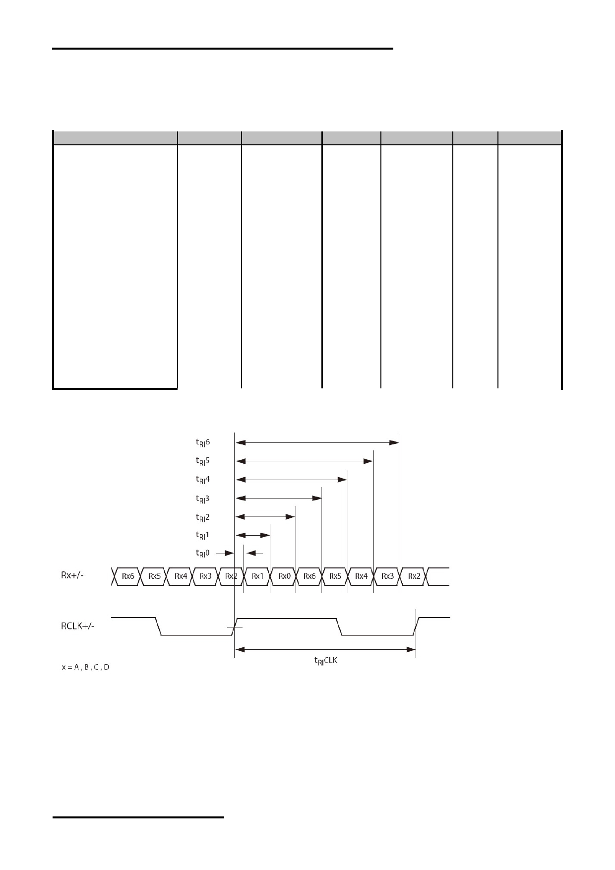
6. AC Characteristics
6.1
AC Characteristics(LVDS)
VDD=5.0V,GND=0V,T a =25 C
Item
Symbol
MIN.
TYP.
MAX.
Unit
Condition
Input CLK period
t RI CLK
8.9
-
50
ns
Input Data Position 0
t RI 0
-0.3
-
+0.3
ns
( tRICLK = 8.9ns )
Input Data Position 1
t RI 1
t RI CLK/7-0.3
t RI CLK/7
t RI CLK/7+0.3
ns
(tRICLK = 8.9ns )
Input Data Position 2
t RI 2
2t RI CLK/7-0.3
2t RI CLK/7
2t RI CLK/7+0.3
ns
(tRICLK = 8.9ns )
Input Data Position 3
t RI 3
3t RI CLK/7-0.3
3t RI CLK/7
3t RI CLK/7+0.3
ns
(tRICLK = 8.9ns )
Input Data Position 4
t RI 4
4t RI CLK/7-0.3
4t RI CLK/7
4t RI CLK/7+0.3
ns
(tRICLK = 8.9ns )
Input Data Position 5
t RI 5
5t RI CLK/7-0.3
5t RI CLK/7
5t RI CLK/7+0.3
ns
(tRICLK = 8.9ns )
Input Data Position 6
t RI 6
6t RI CLK/7-0.3
6t RI CLK/7
6t RI CLK/7+0.3
ns
(tRICLK = 8.9ns )
Input Clock and Data timing Diagram:
NURL: www.topwaydisplay.com
Document Name: LMK104DNEFWU-AKA-Manual-Rev0.1
Page: 6 of 10
TOPWAY
LCD Module User Manual
LMK104DNEFWU-AKA
NURL: www.topwaydisplay.com
Document Name: LMK104DNEFWU-AKA-Manual-Rev0.1
Page: 7 of 10
TOPWAY
LCD Module User Manual
LMK104DNEFWU-AKA
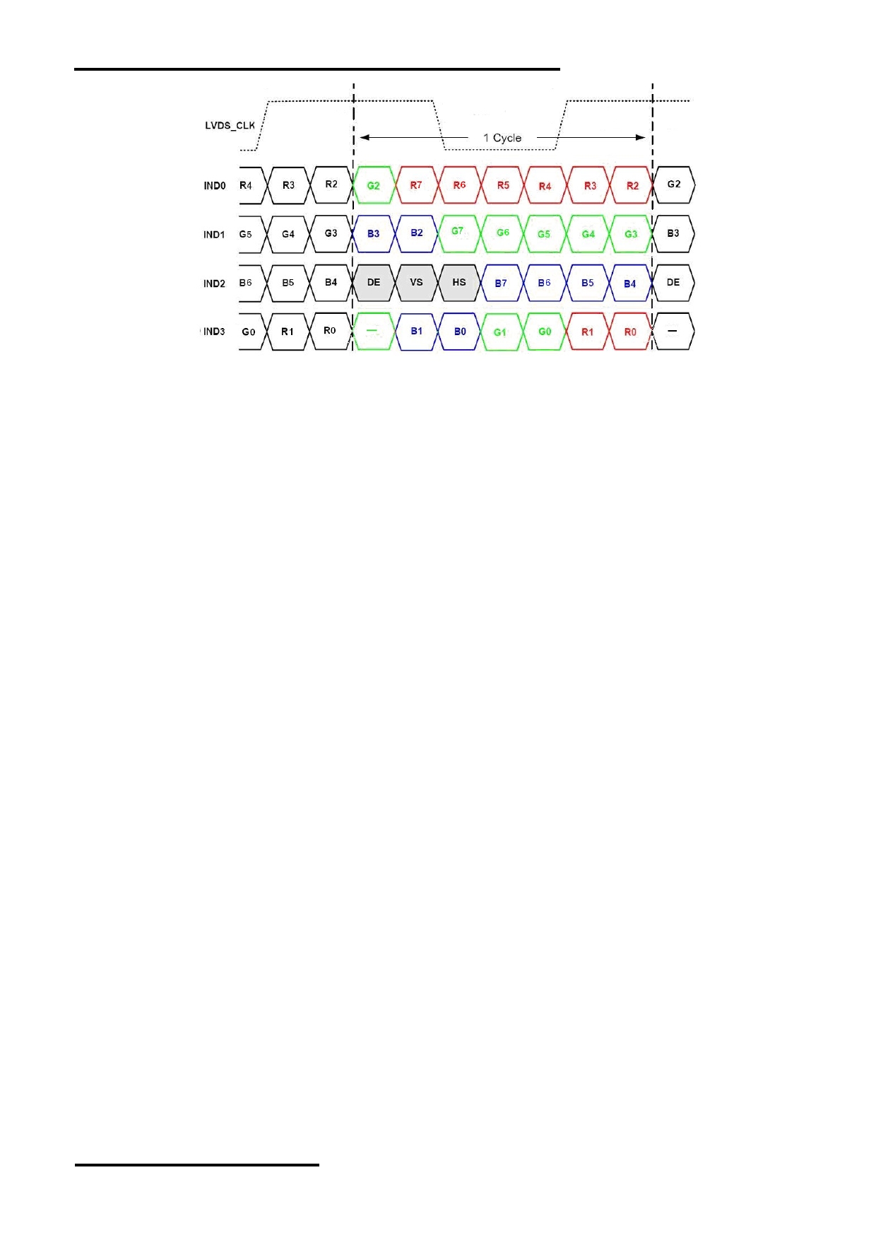
6.2
AC Characteristics(TFT)
HV SYNC MODE
Item
Symbol
MIN.
TYP.
MAX.
Unit
Remark
DCLK Frequency
fclk
35.4
39.6
50.4
MHz
Horizontal Display Area
thd
800
DCLK
One Horizontal Line
th
900
1000
1200
DCLK
HS pulse width
thpw
1
-
40
DCLK
Back Porch
thb
88
DCLK
HS Front Porch
thfp
12
112
312
DCLK
Vertical Display Area
tvd
-
600
-
TH
VS period time
tv
604
628
800
TH
VS pulse width
tvpw
1
-
20
TH
VS Blanking
tvb
39
TH
VS Front Porch
tvfp
1
21
61
TH
DE MODE (Default)
Item
Symbol
Values
Unit
Remark
MIN.
TYP.
MAX.
DCLK Frequency
fclk
32.6
39.6
62.4
MHz
th
890
1000
1300
DCLK
HSD
thd
800
DCLK
thb+thfp
90
200
500
DCLK
tv
610
660
800
TH
VSD
tvd
600
TH
tvb+tvfp
10
60
200
TH
Vertical timing
Horizontal timing
NURL: www.topwaydisplay.com
Document Name: LMK104DNEFWU-AKA-Manual-Rev0.1
Page: 8 of 10
TOPWAY
LCD Module User Manual
LMK104DNEFWU-AKA
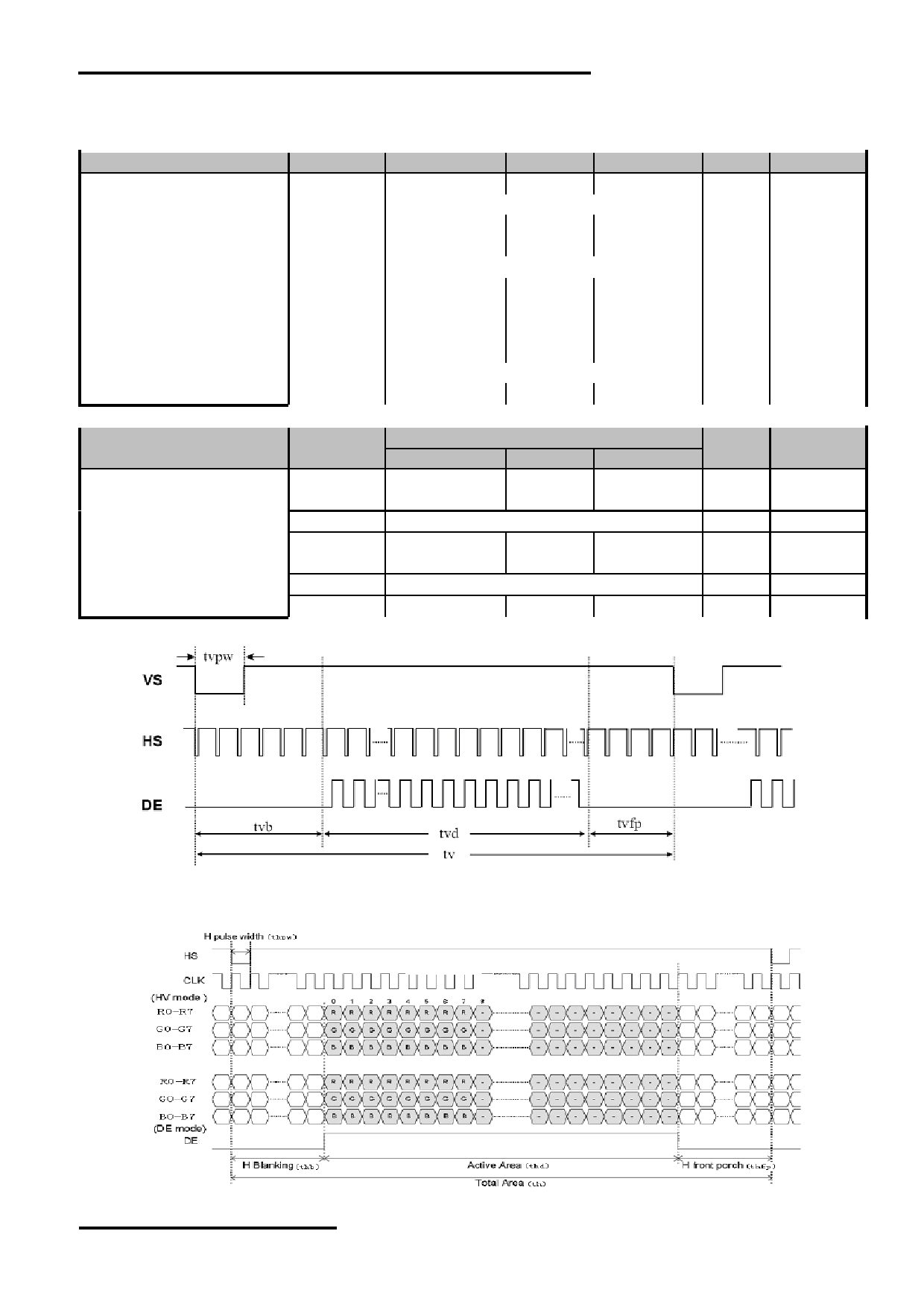
7. Optical Characteristics
Item
Symbol
Condition
MIN.
TYP.
MAX.
UNIT
Note.
θ L
9 o’clock
60
70
-
Viewing angle
θ R
3 o’clock
60
70
-
(CR ≥ 10)
degree
*2
θ T
12 o’clock
50
60
-
θ B
6 o’clock
60
70
-
T f
-
10
15
msec
Response Time
*3
T r
-
15
25
msec
Contrast Ratio
CR
400
500
-
-
Normal
W X
0.259
0.309
0.359
-
*1
Color Chromaticlty
θ=0 o
W Y
0.284
0.334
0.384
-
Luminance
L
250
cd/m 2
*4
Luminance uniformity
U
75
80
-
%
*4
Note:
*1. Definition of Contrast Ratio
The contrast ratio could be calculate by the following expression:
Contrast Ratio (CR) = Luminanc with all pixels white / Luminance with all pixels black
*2 Definition of Viewing Angle
*3 Definition of response time
*4 Definition of Luminance Uniformity
Luminance uniformity (Lu)=
Min. Luminance form pt1~pt9 / Max Luminance form Pt1~pt9
NURL: www.topwaydisplay.com
Document Name: LMK104DNEFWU-AKA-Manual-Rev0.1
Page: 9 of 10

TOPWAY
LCD Module User Manual
LMK104DNEFWU-AKA
8. Precautions for Use of LCD Modules
Please refer to "LCD-Module-Design-Handling-Precaution.pdf".
NURL: www.topwaydisplay.com
Document Name: LMK104DNEFWU-AKA-Manual-Rev0.1
Page: 10 of 10