LMT050DNCFWU-3
LCD Module User Manual
Prepared by:
Checked by:
Approved by:
Gong huimei
Date: 2024-01-17
Date:
Date:
Rev. Descriptions
Edit
Release Date
0.1
Preliminary
Gong huimei 2024-01-17
URL: www.topwaydisplay.com
Document Name: LMT050DNCFWU-3 Manual-Rev0.1
Page: 1 of 11

TOPWAY
LCD Module User Manual
LMT050DNCFWU-3
Table of Content
1. General Specification....................................................................................................................3
2. Block Diagram................................................................................................................................3
3. Terminal Functions........................................................................................................................4
3.1 Interface......................................................................................................................................... 4
4. Absolute Maximum Ratings......................................................................................................... 5
5. Electrical Characteristics..............................................................................................................5
5.1 DC Characteristics.........................................................................................................................5
5.2 LED Backlight Circuit Characteristics............................................................................................5
5.3 Power ON/OFF Sequence.............................................................................................................6
6. AC Characteristics.........................................................................................................................7
6.1 AC Timing...................................................................................................................................... 7
6.2 Data Input format........................................................................................................................... 8
7. Optical Characteristics..................................................................................................................9
URL: www.topwaydisplay.com
Document Name: LMT050DNCFWU-3 Manual-Rev0.1
Page: 2 of 11
TOPWAY
LCD Module User Manual
LMT050DNCFWU-3
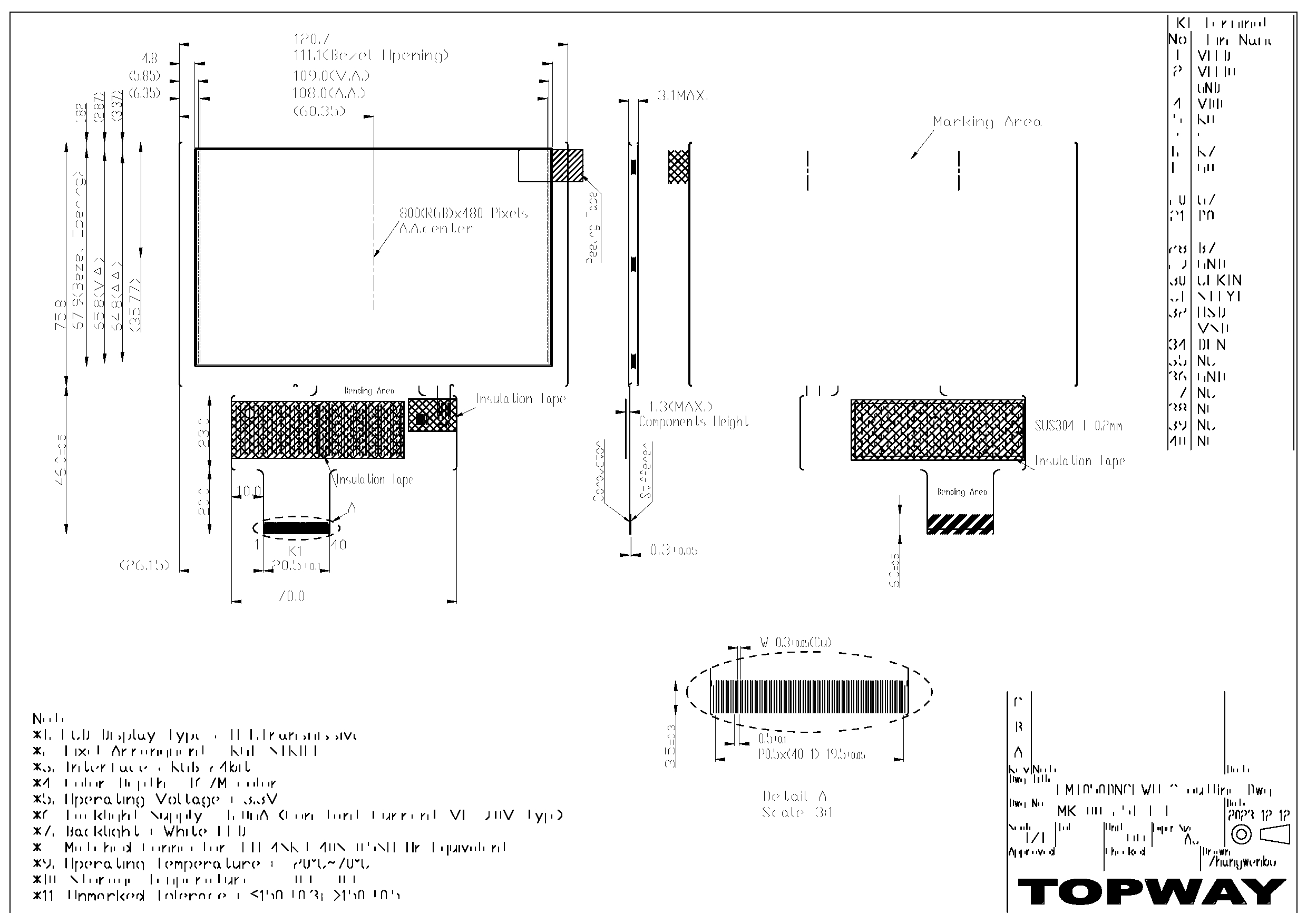
1. General Specification
Screen Size(Diagonal) :
5.0 ”
Active Area :
108 x 64.8 (mm)
Number of dots :
800(RGB) x 480
Pixel Pitch :
0.135 x 0.135 (mm)
Color Depth :
16.7M colors
Display Technology :
a-Si TFT active matrix
Display Mode :
Normal White, Transmissive
Display Interface :
RGB_24bit
Viewing Direction :
6H (*1) (gray scale inverse)
12H (*2)
Surface Treatment :
Anti-Glare
Operating Temperature :
-20 ~ +70°C
Storage Temperature :
-30 ~ +80°C
Note:
*1. For saturated color display content (eg. pure-red, pure-green, pure-blue, or pure-colors-combinations).
*2. For “color scales” display content.
*3. Color tone may slightly change by Temperature and Driving Condition.
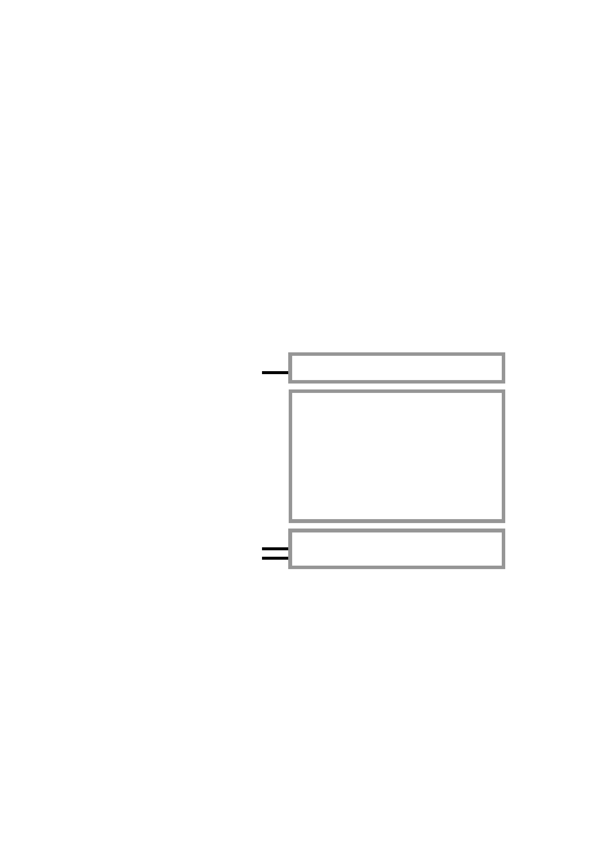
2. Block Diagram
VLED-, VLED+
Backlight Circuit
800(x3) x 480 pixels
TFT Panel
R0~R7, G0~G7, B0~B7
VDD, GND
TFT Driver
CLKIN, HSD, VSD, DEN,STBYB
URL: www.topwaydisplay.com
Document Name: LMT050DNCFWU-3 Manual-Rev0.1
Page: 3 of 11

TOPWAY
LCD Module User Manual
LMT050DNCFWU-3
3. Terminal Functions
3.1 Interface
Pin No. Pin Name
I/O
Descriptions
1
VLED-
P
Backlight LED Cathode supply
2
VLED+
P
Backlight LED Anode supply
3
GND
P
Power Ground (0V)
4
VDD
P
Positive Power Supply
5
R0
:
:
I
Red color data input
12
R7
13
G0
:
:
I
Green color data input
20
G7
21
B0
:
:
I
Blue color data input
28
B7
29
GND
P
Power Ground (0V)
30
CLKIN
I
Clock for input data. Data latched at falling edge of this signal.
Standby mode.
31
STBYB
I
STBYB=“1”: Normally operation.
STBYB=“0”: Standby mode .Timing controller, source driver will
turn off, all output are High-Z.
32
HSD
I
Horizontal Sync signal input
33
VSD
I
Vertical Sync Signal Input
34
DEN
I
Data input enable. Effective only in DE mode.
35
NC
-
No connection, leave open
36
GND
P
Power Ground (0V)
37
NC
38
NC
39
NC
-
No connection, leave open
40
NC
Note:
*1: I/O definition: I---Input, O---Output, P---Power/Ground
*2: Interface: HS, VS mode (default)
URL: www.topwaydisplay.com
Document Name: LMT050DNCFWU-3 Manual-Rev0.1
Page: 4 of 11
TOPWAY
LCD Module User Manual
LMT050DNCFWU-3
4. Absolute Maximum Ratings
Items
Symbol
Min.
Max.
Unit
Condition
Supply Voltage
V DD
-0.5
+3.96
V
GND = 0V
Operating Temperature
T OP
-20
+70
℃
No Condensation
Storage Temperature
T ST
-30
+80
℃
No Condensation
Cautions:
Any Stresses exceeding the Absolute Maximum Ratings may cause substantial damage to the device. Functional
operation of this device at other conditions beyond those listed in the specification is not implied and prolonged exposure
to extreme conditions may affect device reliability.
5. Electrical Characteristics
5.1 DC Characteristics
GND=0V, V DD =3.3V, T OP =25 ℃
Items
Symbol
MIN.
TYP.
MAX.
Unit Applicable Pin
Operating Voltage
VDD
3.2
3.3
3.4
V
VDD
Input High Voltage
V IH
0.7xVDD
-
VDD
V
Input pins
Input Low Voltage
V IL
GND
-
0.3xVDD
V
Input pins
Output Signal Low Voltage
V oH
-
-
GND+0.4
V
Output Signal High Voltage
V IL
VDD-0.4
-
-
V
Operating Current (*1)
I DD
-
90
-
mA
All black
Note.
*1. For different LCM, the value may have a bit of difference.
*2. To test the current dissipation, use “all Black Pattern”.
5.2 LED Backlight Circuit Characteristics
If=120mA, T OP =25 ℃
Items
Symbol
MIN.
TYP.
MAX.
Unit Note
Forward Voltage
Vf
-
9.0
9.9
V
Forward Current
If
-
120
-
mA
Life Time
-
-
40000
-
hr
Cautions:
Exceeding the recommended driving current could cause substantial damage to the backlight and shorten its lifetime.
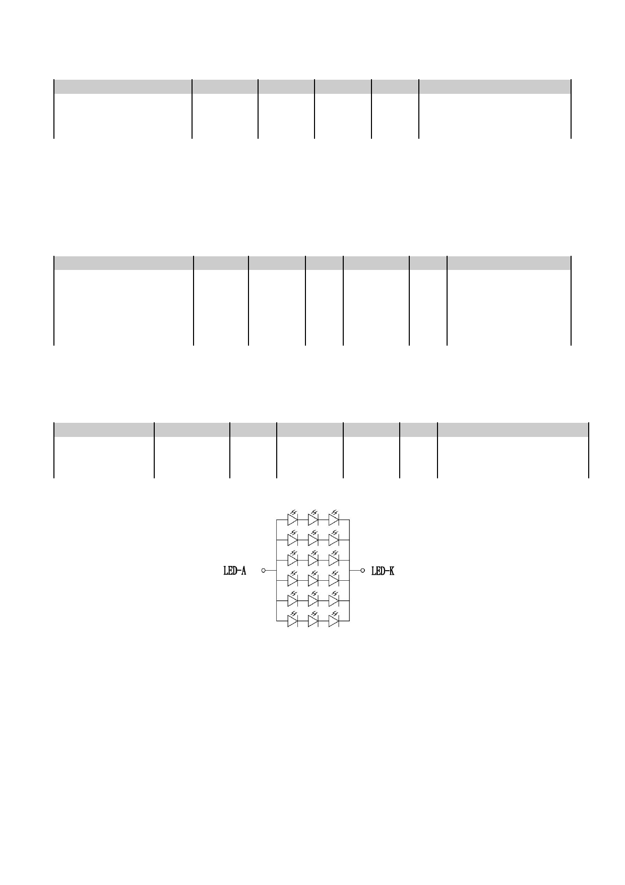
Backlight Circuit Diagram
No. of LEDs = 3x6 pcs
URL: www.topwaydisplay.com
Document Name: LMT050DNCFWU-3 Manual-Rev0.1
Page: 5 of 11
TOPWAY
LCD Module User Manual
LMT050DNCFWU-3
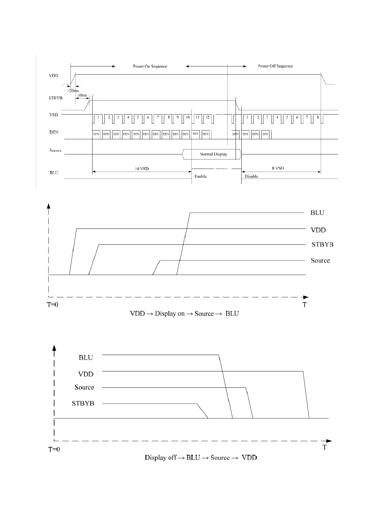
5.3 Power ON/OFF Sequence
Power On/Off Sequence
Power On Sequence
Power OFF Sequence
URL: www.topwaydisplay.com
Document Name: LMT050DNCFWU-3 Manual-Rev0.1
Page: 6 of 11
TOPWAY
LCD Module User Manual
LMT050DNCFWU-3
6. AC Characteristics
6.1 AC Timing
GND=0V, V DD =3.3V, T OP =25 ℃
Item
Symbol
MIN.
TYP.
MAX.
Unit
Remark
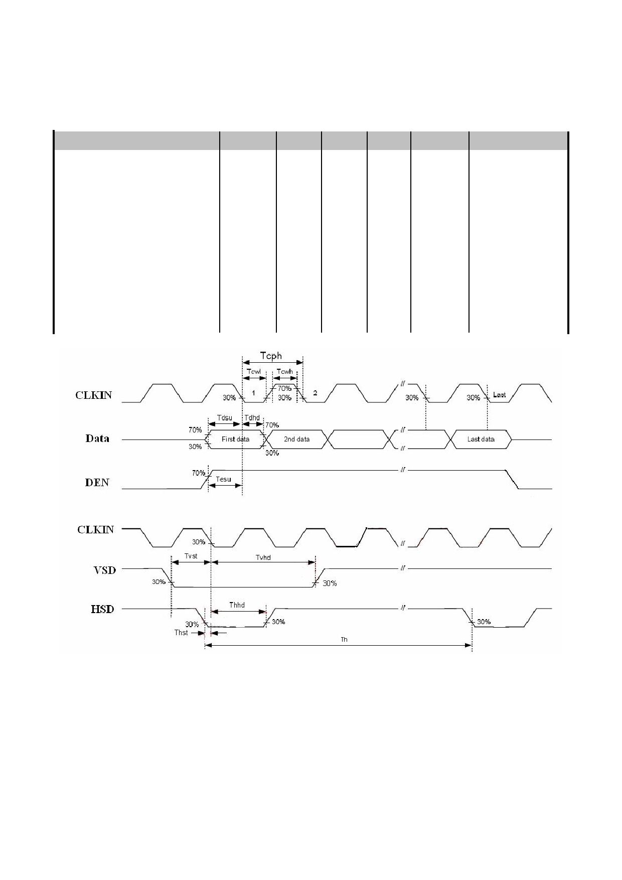
HSD setup time
Thst
8
-
-
ns
HSD hold time
Thhd
8
-
-
ns
VSD setup time
Tvst
8
-
-
ns
VSD hold time
Tvhd
8
-
-
ns
Data setup time
Tdsu
8
-
-
ns
Data hole time
Tdhd
8
-
-
ns
DE setup time
Tesu
8
-
-
ns
VDD Power On Slew rate
Tpor
-
-
20
ms
CLKIN cycle time
Tcph
20
-
-
ns
CLKIN pulse duty
Tcwh
40
50
60
%
Input Clock and Data Timing Diagram
URL: www.topwaydisplay.com
Document Name: LMT050DNCFWU-3 Manual-Rev0.1
Page: 7 of 11
TOPWAY
LCD Module User Manual
LMT050DNCFWU-3
6.2 Data Input format
Item
Symbol
MIN.
TYP.
MAX.
Unit
Remark
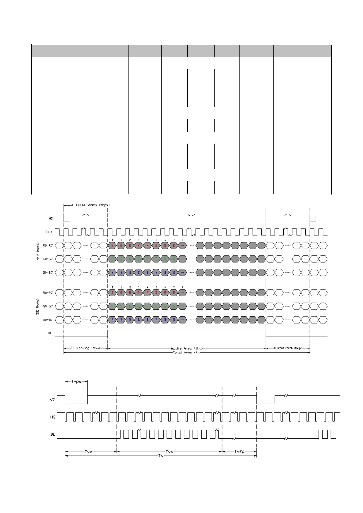
Horizontal Display Area
thd
800
DCLK
CLKIN Frequency
fclk
-
30
50
MHz
One Horizontal Line
th
889
928
1143
CLKIN
HSD pulse width
thpw
1
48
255
CLKIN
HSD Blanking
thb
88
CLKIN
HSD Front Porch
thfp
1
40
255
CLKIN
Vertical Display Area
tvd
480
TH
VSD period time
tv
513
525
767
TH
VSD pulse width
tvpw
3
3
255
TH
VSD Blanking
tvb
32
TH
VSD Front Porch
tvfp
1
13
255
TH
Horizontal input timing diagram
Vertical input timing diagram
URL: www.topwaydisplay.com
Document Name: LMT050DNCFWU-3 Manual-Rev0.1
Page: 8 of 11
TOPWAY
LCD Module User Manual
LMT050DNCFWU-3
7. Optical Characteristics
Item
Symbol
Condition
MIN.
TYP.
MAX.
UNIT
Note.
θ T
40
50
-
Viewing angle
θ B
60
70
-
(CR ≥ 10)
degree
Note 2,3
θ L
60
70
-
θ R
60
70
-
Contrast ratio
CR
θ=0 o
500
600
-
-
Note 3
T on
Response Time
25 ℃
-
20
30
ms
Note 4
T off
X
0.275 0.325 0.375
White
Y
0.313 0.363 0.413
X
0.556 0.616 0.656
Red
Y
Backlight
0.285 0.335 0.385
Chromaticlty
is on
-
Note 1,5
X
0.256 0.306 0.356
Green
Y
0.517 0.567 0.617
X
0.086 0.136 0.186
Blue
Y
0.108 0.158 0.208
Luminance
L
-
1100
-
cd/m 2
Note 1,6
NTSC
-
50
%
Note 5
Luminance uniformity
U
80
85
-
%
Note 1,7
Test Conditions:
1. If= 120mA, Vf=9.0V, and the ambient temperature is 25 ℃
2. The test systems refer to Note 1 and Note 2.
URL: www.topwaydisplay.com
Document Name: LMT050DNCFWU-3 Manual-Rev0.1
Page: 9 of 11
TOPWAY
LCD Module User Manual
LMT050DNCFWU-3
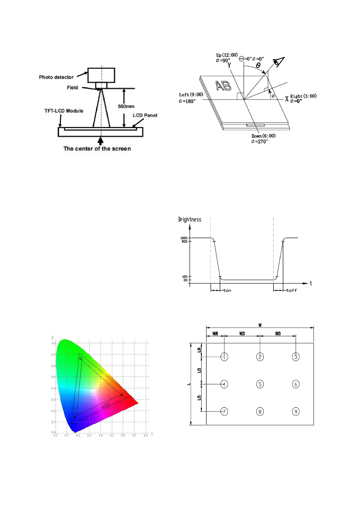
Note 1:
Note 2:
Definition of optical measurement system.
The definition of viewing angle:
The optical characteristics should be measured in dark room.
Refer to the graph below marked by θ and Ф
After 5 Minutes operation, the optical characteristics
are measured at the center point of the LCD screen.
Note 3:
The definition of contrast ratio (Test LCM using SR-3A (1°)):
Note 4:
Contrast
Luminance When LCD is at “White” state
Definition of Response time. (Test LCD using BM-7A(2°)):
Ratio(CR)
=
Luminance When LCD is at “Black” state
The output signals of photo detector are measured
(Contrast Ratio is measured in optimum common electrode
when the input signals are changed from
voltage)
“black” to “white”(falling time)
and from “white” to “black”(rising time), respectively.
The response time is defined as
the time interval between the 10% and 90% of amplitudes.Refer to
figure as below.
Note 5:
Note 6:
Definition of Color of CIE1931 Coordinate and NTSC Ratio.
The luminance uniformity is calculated by using following formula.
△ Bp = Bp (Min.) / Bp (Max.)×100 (%)
Color gamut:
Bp (Max.) = Maximum brightness in 9 measured spots
Area of RGB triangle
S=
X100%
Bp (Min.) = Minimum brightness in 9 measured spots .
Area of NTSC triangle
Note 7:
Measured the luminance of white state at center point
URL: www.topwaydisplay.com
Document Name: LMT050DNCFWU-3 Manual-Rev0.1
Page: 10 of 11

TOPWAY
LCD Module User Manual
LMT050DNCFWU-3
Warranty
This product has been manufactured to our company’s specifications as a part for use in your company’s general
electronic products. It is guaranteed to perform according to delivery specifications. For any other use apart from
general electronic equipment, we cannot take responsibility if the product is used in medical devices, nuclear power
control equipment, aerospace equipment, fire and security systems, or any other applications in which there is a direct
risk to human life and where extremely high levels of reliability are required. If the product is to be used in any of the
above applications, we will need to enter into a separate product liability agreement.
- We cannot accept responsibility for any defect, which may arise form additional manufacturing of the product
(including disassembly and reassembly), after product delivery.
- We cannot accept responsibility for any defect, which may arise after the application of strong external force to the
product.
- We cannot accept responsibility for any defect, which may arise due to the application of static electricity after the
product has passed our company’s acceptance inspection procedures.
- When the product is in CCFL models, CCFL service life and brightness will vary according to the performance of the
inverter used, leaks, etc. We cannot accept responsibility for product performance, reliability, or defect, which may
arise.
- We cannot accept responsibility for intellectual property of a third part, which may arise through the application of
our product to our assembly with exception to those issues relating directly to the structure or method of
manufacturing of our product.
URL: www.topwaydisplay.com
Document Name: LMT050DNCFWU-3 Manual-Rev0.1
Page: 11 of 11
