LMT070DICFWD-NAA
LCD Module User Manual
Prepared by:
Checked by:
Approved by:
HT LIU
Date: 2016-04-05
Date:
Date:
Rev. Descriptions
Release Date
0.1
Preliminary release
2010-11-16
0.2
Update Jumper Setting
2010-11-18
0.3
Typing Correction in General Spec
2010-12-27
0.4
Typing Correction in General Spec
2011-05-13
0.5
Refine 7.1 Timing Characteristics
2012-02-09
0.6
Add 6.2 Touch panel Characteristics Details
2013-01-10
0.7
Typing Correction
2016-4-6
URL: www.topwaydisplay.com
Document Name: LMT070DICFWD-NAA-Manual-Rev0.7
Page: 1 of 9

TOPWAY
LCD Module User Manual
LMT070DICFWD-NAA
Table of Content
1. Applications ........................................................................................................................... 3
2. General Specification ............................................................................................................ 3
3. Block Diagram ........................................................................................................................ 3
4. Terminal Function .................................................................................................................. 4
5. Absolute Maximum Ratings .................................................................................................. 5
6. Electrical Characteristics ...................................................................................................... 5
6.1
DC Characteristics ............................................................................................................ 5
6.2
Touch panel Characteristics.............................................................................................. 5
7. AC Characteristics ................................................................................................................. 6
7.1
Timing Characteristics ...................................................................................................... 6
7.2
Input Clock and Data Timing Diagram .............................................................................. 6
7.3
Timing ............................................................................................................................... 7
7.4
Data Input Format ............................................................................................................. 7
7.5
Optical Characteristics ...................................................................................................... 8
8. Precautions of using LCD Modules ...................................................................................... 9
9. Appendix <Inspection items and criteria for appearance defect> ..................................... 9
URL: www.topwaydisplay.com
Document Name: LMT070DICFWD-NAA-Manual-Rev0.7
Page: 2 of 9

TOPWAY
LCD Module User Manual
LMT070DICFWD-NAA
1. Applications
This Module is designed for application which require high quality flat panel displays. It is
also a good substitute for many outmoded CSTN module in the industrial application.
2. General Specification
Signal Interface :
Digital 24-bits RGB
Display Technology :
a-Si TFT active matrix
Display Mode :
Transmissive / Normal White
Screen Size(Diagonal) :
7.0”
Outline Dimension :
190.0 x 112.0 x 13.4 (mm)
(see attached drawing for details)
Active Area :
154.08 x 85.92 (mm)
Number of dots :
800 x 3 (RGB) x 480
Pixel Pitch :
0.0642 x 0.179 (mm)
Pixel Configuration :
RGB Stripe
Backlight :
LED
Surface Treatment :
Anti-Glare Treatment
Viewing Direction :
6 o’clock
Touch Panel:
4wire resistive
Operating Temperature :
-20 ~ +70°C
Storage Temperature :
-30 ~ +80°C
3. Block Diagram
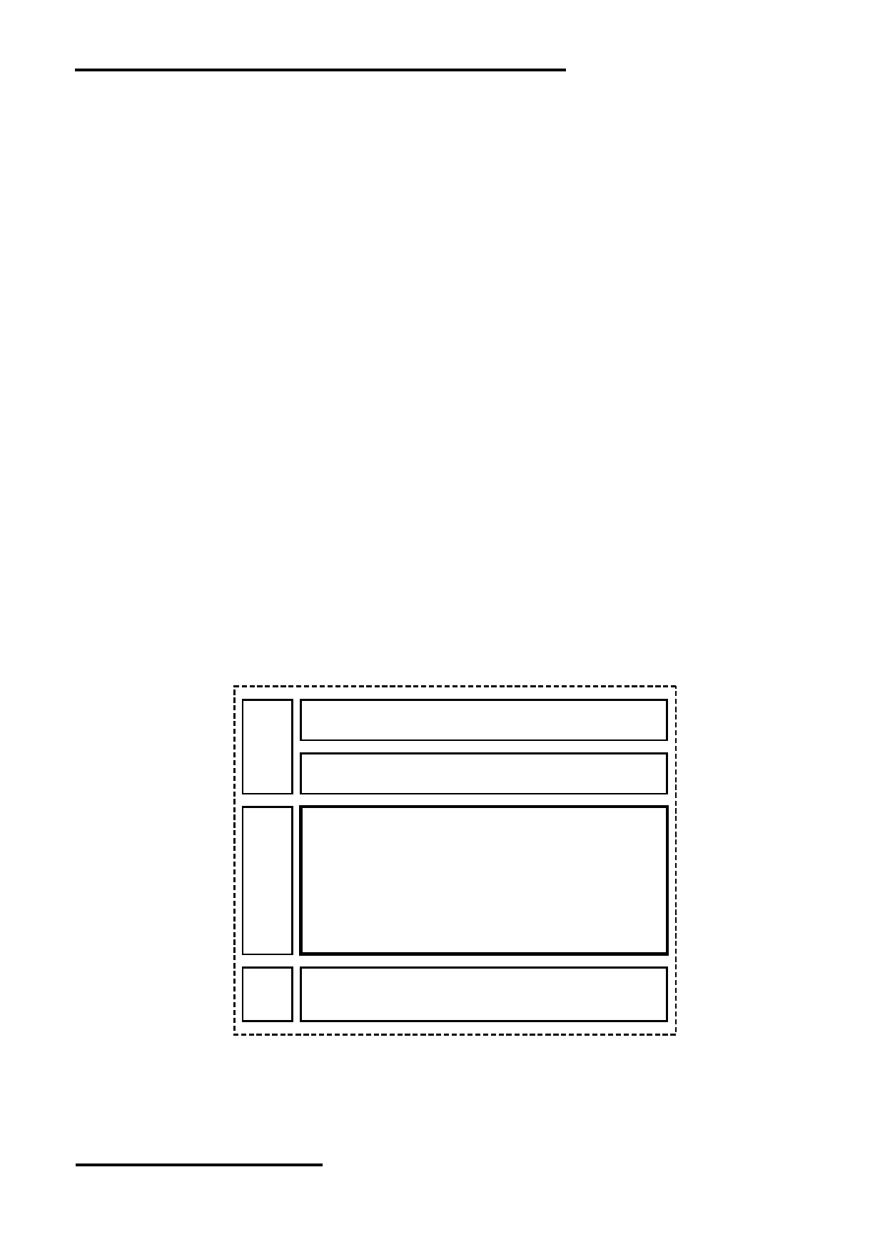
Touch Panel
Backlight Circuit
7” TFT Panel
Source Driver
URL: www.topwaydisplay.com
Document Name: LMT070DICFWD-NAA-Manual-Rev0.7
Page: 3 of 9

TOPWAY
LCD Module User Manual
LMT070DICFWD-NAA
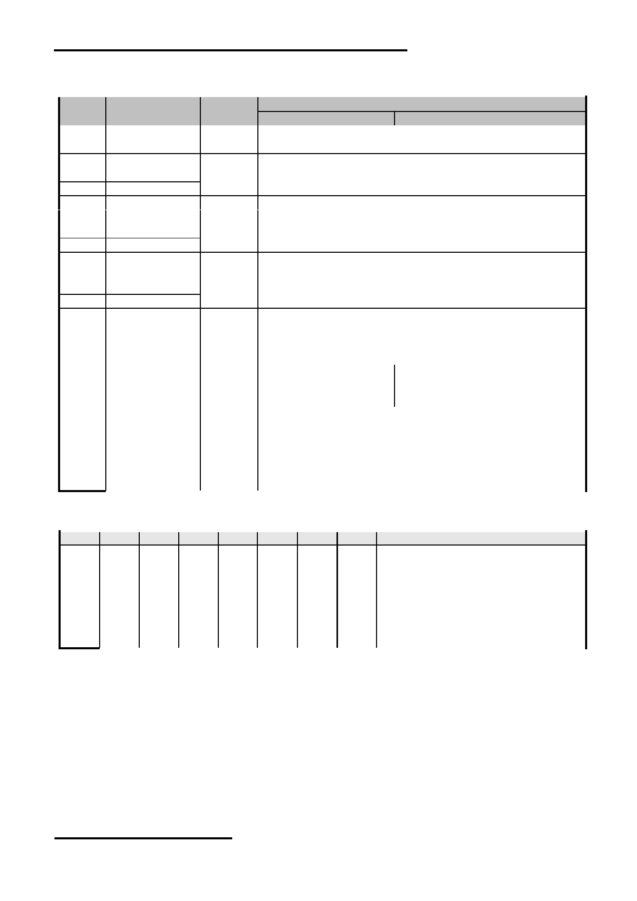
4. Terminal Function
K2
Descriptions
Pin No.
Pin Name
I/O
DE Mode <default>
Sync Mode
1
VCC
Positive Power Supply
2
VCC
Power
3
B0
Blue Data
:
:
Input
10
B7
11
GND
Power
Power Supply GND (0V)
12
G0
Green Data
:
:
Input
19
G7
20
GND
Power
Power Supply GND (0V)
21
R0
Red Data
:
:
Input
28
R7
29
GND
Power
Power Supply GND (0V)
30
LED_ADJ
Input
LED driver enable control
31
NC
--
No connection, leave open
32
NC
--
No connection, leave open
33
DE
Input
DE Signal Input
Pull Lo
34
VS
Input
Pull Hi
Vertical Sync Input
35
HS
Input
Pull Hi
Horizontal Sync Input
36
DCLK
Input
Data Clock Input
Data shall be latched at the falling edge of DCLK.
37
TSXM
Passive Touch Screen X- terminal
38
TSXP
Passive Touch Screen X+ terminal
39
TXYM
Passive Touch Screen Y- terminal
40
TSYP
Passive Touch Screen Y+ terminal
Jumper Setting
JP1
JP2
JP3
JP4
JP5
JP6
JP7
JP8 Function Descriptions
CLOSE OPEN
-
-
-
-
-
-
DE MODE <default>
OPEN CLOSE
-
-
-
-
-
-
SYNC MODE
-
-
CLOSE OPEN OPEN CLOSE
-
-
Up to down, left to right <default>
-
-
OPEN CLOSE CLOSE OPEN
-
-
Down to up, right to left
-
-
OPEN CLOSE OPEN CLOSE
-
-
Up to down, right to left
-
-
CLOSE OPEN CLOSE OPEN
-
-
Down to up, left to right
-
-
-
-
-
-
CLOSE OPEN Disable internal dithering function <default>
-
-
-
-
-
-
OPEN CLOSE Enable internal dithering function
Note:
* 1. When select DE mode, MODE=”1”, VS and HS must pull high.
When select SYNC mode, MODE= “0”, DE must be grounded.
URL: www.topwaydisplay.com
Document Name: LMT070DICFWD-NAA-Manual-Rev0.7
Page: 4 of 9

TOPWAY
LCD Module User Manual
LMT070DICFWD-NAA
5. Absolute Maximum Ratings
Items
Symbol
Min.
Max.
Unit
Condition
Power Supply voltage
V CC
-0.3
6.0
V
Operating Temperature
T OP
-20
70
C
No Condensation
Storage Temperature
T ST
-30
80
C
No Condensation
Note:
*1. This rating applies to all parts of the module. And should not be exceeded.
*2. The operating temperature only guarantees operation of the circuit. The contrast, response speed, and
the other specification related to electro-optical display quality is determined at the room temperature,
T OP =25.
*3. Ambient temperature when the backlight is lit (reference value)
*4. Any Stresses exceeding the Absolute Maximum Ratings may cause substantial damage to the device.
Functional operation of this device at other conditions beyond those listed in the specification is not
implied and prolonged exposure to extreme conditions may affect device reliability.
6. Electrical Characteristics
6.1 DC Characteristics
Top=25 ℃ , GND=0V
Items
Symbol
Min.
Typ.
Max.
Unit
Remark
Power Supply Voltage
V CC
4.5
5.0
5.5
V
(*1)
Input logic high voltage
V IH
3.0
-
3.6
V
Input logic low voltage
V IL
0
-
0.7
V
Logic Supply (VDD)
I VDD
-
255
640
mA
LED_ADJ=Hi (*3)
Note:
*1. Never apply logic signal before the VCC.
*2. PWM signal (Freq<800Hz) could be applied to LED_ADJ pin for backlight brightness control, where its
life time could be extend by lower its brightness.
6.2 Touch panel Characteristics
T OP =25 C
Items
MIN.
TYP.
MAX.
Unit Applicable Pin
Terminal resistance
100
-
900
Ω
X- terminal
200
-
1200
Ω
Y- terminal
Operating Voltage
-
-
7
V
-
Response time
-
-
10
ms
-
Operating Force
100
-
160
g
-
Life Time
-
1,000,000
-
times -
Cautions:
Exceeding the recommended Condition could cause substantial damage to the touch panel and shorten its
lifetime.
URL: www.topwaydisplay.com
Document Name: LMT070DICFWD-NAA-Manual-Rev0.7
Page: 5 of 9

TOPWAY
LCD Module User Manual
LMT070DICFWD-NAA
7. AC Characteristics
7.1 Timing Characteristics
Item
Symbol MIN. TYP. MAX.
Unit
Remark
HS setup time
Thst
8
-
-
ns
HS hold time
Thhd
8
-
-
ns
VS setup time
Tvst
8
-
-
ns
VS hold time
Tvhd
8
-
-
ns
Data setup time
Tdsu
8
-
-
ns
Data hole time
Tdhd
8
-
-
ns
DE setup time
Tesu
8
-
-
ns
V CC Power On Slew rate
TPOR
-
-
20
ms
From 0 to 90% V CC
DCLK cycle time
Tcph
20
-
-
ns
DCLK pulse duty
Tcwh
40
50
60
%
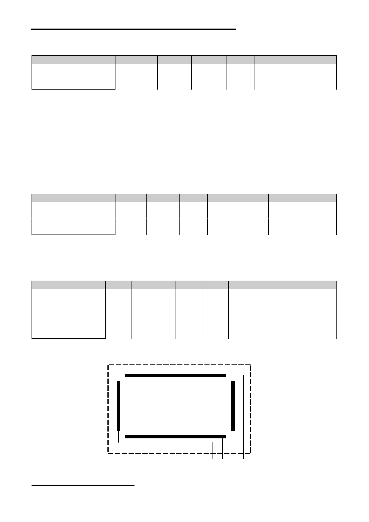
7.2 Input Clock and Data Timing Diagram
URL: www.topwaydisplay.com
Document Name: LMT070DICFWD-NAA-Manual-Rev0.7
Page: 6 of 9

TOPWAY
LCD Module User Manual
LMT070DICFWD-NAA
7.3 Timing
Item
Symbol
MIN.
TYP.
MAX.
Unit
Remark
Horizontal Display Area
thd
-
800
-
DCLK
DCLK Frequency
fclk
26.4
33.3
46.8
MHz
One Horizontal Line
th
862
1056
1200
DCLK
HS pulse width
thpw
1
-
40
DCLK
HS Blanking
thb
46
46
46
DCLK
HS Front Porch
thfp
16
210
354
DCLK
Vertical Display Area
tvd
-
480
-
TH
VS period time
tv
510
525
650
TH
VS pulse width
tvpw
1
-
20
TH
VS Blanking
tvb
23
23
23
TH
VS Front Porch
tvfp
7
22
147
TH
7.4 Data Input Format
Figure 6-2-1 Horizontal input timing diagram.
Figure 6-2-2 Vertical input timing diagram.
URL: www.topwaydisplay.com
Document Name: LMT070DICFWD-NAA-Manual-Rev0.7
Page: 7 of 9

TOPWAY
LCD Module User Manual
LMT070DICFWD-NAA
7.5 Optical Characteristics
Item
Symbol
Condition
MIN.
TYP.
MAX.
UNIT
Note.
θ L
9 o’clock
60
70
-
Viewing angle
θ R
3 o’clock
60
70
-
(CR ≥ 10)
degree
*2
θ T
12 o’clock
40
50
-
θ B
6 o’clock
60
70
-
T f
-
10
20
msec
Response Time
*3
T r
-
15
30
msec
Contrast ratio
CR
400
500
-
-
Normal
W X
0.26
0.31
0.26
-
*1
Color chromaticity
θ=0 o
W Y
0.28
0.33
0.38
-
Luminance
L
-
250
-
cd/m 2
*4
Luminance uniformity
Y U
70
75
-
%
*4
Note:
*1. Definition of Contrast Ratio
The contrast ratio could be calculate by the following expression:
Contrast Ratio (CR) = Luminance with all pixels white / Luminance with all pixels black
*2 Definition of Viewing Angle
*3 Definition of response time
*4 Definition of Luminance Uniformity
Luminance uniformity (Lu)=
Min. Luminance form pt1~pt9 / Max Luminance form Pt1~pt9
*5. Given parameter measured without touch panel.
URL: www.topwaydisplay.com
Document Name: LMT070DICFWD-NAA-Manual-Rev0.7
Page: 8 of 9

TOPWAY
LCD Module User Manual
LMT070DICFWD-NAA
8. Precautions of using LCD Modules
Please refer to "LCD-Module-Design-Handling-Precaution.pdf".
9. Appendix <Inspection items and criteria for appearance defect>
Bright/Dark Dots:
Defect Type
Specification
Major
Minor
Bright Dots
N≤ 2
●
Dark Dots
N≤ 3
●
Total Bright and Dark Dots
N≤ 4
●
Note: 1. The definition of dot: The size of a defective dot over 1/2 of whole dot is regarded as one defective
dot.
2. Bright dot: Dots appear bright and unchanged in size in which LCD panel is displaying under black
pattern.
3. Dark dot: Dots appear dark and unchanged in size in which LCD panel is displaying under pure red,
green, blue pattern.
URL: www.topwaydisplay.com
Document Name: LMT070DICFWD-NAA-Manual-Rev0.7
Page: 9 of 9