技术白皮书 - STM32单片机点亮 7 寸TFT液晶屏
1 概要
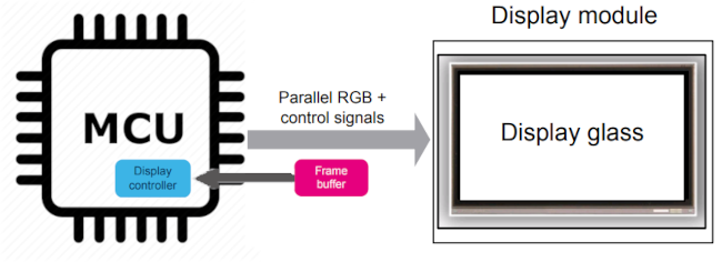
此白皮书详细讲述使用STM32H7系列单片机,如何使用单片机带有的 LTDC 控制器驱动7寸 LMT070ENMFWA-NND-2。内容包含液晶屏初始化,LTDC配置,背光、时钟和触摸屏的设置。
2 硬件介绍
Microcontroller: STM32H743ZI (或使用类似带有液晶屏控制器和足够处理能力的MCU)
Display: LMT070ENMFWA-NND-2 TFT LCD (800x480, RGB888 接口)
Touch Panel: 电容触摸屏(I2C接口)
External RAM: SDRAM (帧缓存)
2.1 STM32H743ZI MCU
STM32H743ZI 是一款 ARM Cortex-M7 单片机,具有高时钟频率、大内存和丰富的外设功能,十分适合嵌入式系统的应用,其特点包括:
- 高处理能力的 ARM Cortex-M7 核心
- 高达 480 MHz 的单片机主频
- 自带液晶显示控制器
- 2 MB Flash、1 MB RAM
- 高速通讯接口
2.2 LMT070ENMFWA-NND-2 TFT LCD
拓普微的 LMT070ENMFWA-NND-2 是一款 7寸 IPS TFT液晶显示屏,自带了液晶驱动芯片和 LED 背光。
- 液晶显示: a-Si IPS TFT LCD
- 分辨率: 1024 x 3(RGB) x 600
- 接口: 24位 RGB 并行接口
- 背光: 白 LED
- 电容触摸屏: ILI2511 驱动 IC
3 硬件接口和配置
3.1 TFT LCD 接口
LMT070ENMFWA-NND-2 的并行接口包含24位RGB数据,控制信号,同步信号等。
数据信号: R0-R7, G0-G7, B0-B7 (每种颜色8位)
同步信号: HS (行同步), VS (场同步), DE (数据使能)
时钟信号: DCLK
控制信号: MODE (DE/SYNC 选择), L/R (左/右选择), U/D (上/下选择), DITHB (Dithering 设置), RESET (重置)
3.2 电容触摸屏接口
电容触摸屏通过 I2C 接口连接系统
I2C 信号: SDA (I2C 数据), SCL (I2C 时钟)
其他信号: RST (触摸重置), INT (中断)
3.3 STM32H743ZI 设置
通过内置的 LTDC STM32H743ZI单片机可直接控制 TFT 液晶显示屏。在使用前,我们需要根据 LMT070ENMFWA-NND-2 的参数,配置好时序、数据格式和其他控制信号。
LCD 控制器设置:
设置行场时序参数
配置时钟和数据格式
开启需要的中断服务
GPIO 配置:
根据 RGB 数据需求配置 GPIO 引脚
配置 GPIO 引脚产生控制与同步信号 (HS, VS, DE, MODE 等.)
配置 GPIO 引脚用于 I2C (SDA, SCL) 通讯
I2C 设置:
初始化 I2C 通讯
设置时钟频率和寻址模式
3.4 硬件连接
| STM32H7 Pin | LCD Pin | Function | Notes |
|---|---|---|---|
| LTDC_R[0..7] | R0-R7 | 红色数据 | RGB888 |
| LTDC_G[0..7] | G0-G7 | 绿色数据 | |
| LTDC_B[0..7] | B0-B7 | 蓝色数据 | |
| LTDC_CLK | DCLK | 像素点时钟 | ~33-50MHz |
| LTDC_HSYNC | HSYNC | 行同步 | |
| LTDC_VSYNC | VSYNC | 场同步 | |
| LTDC_DE | DE | 数据使能 | |
| VDD (3.3V) | VDD | 供电 | |
| GND | GND | 地 | |
| TIMx_CHx (PWM Out) | VLED+ | 背光控制 (PWM) | |
| GPIO (Open drain) | VLED- | 背光 地 | |
| I2C1_SCL | TP_SCL | 触摸 I2C 时钟 | |
| I2C1_SDA | TP_SDA | 触摸 I2C 数据 | |
| GPIO_EXTI | TP_INT | 触摸中断 |
Optional |
4. 具体实现
4.1 初始化
以下是使用 HAL 库实现主要部分的初始化流程 (大部分的功能可以用 STM32CubeMX 生成)
上电步骤:
- 数字/模拟电信号: DVDD (3.3V) and AVDD.
- 门驱动: 先VGL 然后 VGH.
- 背光: 以上供电稳定后,接入 VLED+ 和 VLED–.
初始化步骤:
- HAL 和系统时钟 (PLL3 for LTDC)
- 使用兼容 1024x600 分辨率的时钟参数初始化 LTDC
- FMC (SDRAM) 初始化帧缓存
- I2C 初始化
- 背光 (PWM) 时钟初始化
4.2 软件例程
4.2.1 HAL 初始化和系统时钟适配
#include "stm32h7xx_hal.h"
/* System Clock Configuration
This configuration uses PLLs to generate the system clock as well as the LTDC pixel clock.
Adjust PLL3 parameters as needed for your target pixel clock (for example, ~33-50MHz for DCLK).
*/
void SystemClock_Config(void)
{
RCC_OscInitTypeDef RCC_OscInitStruct = {0};
RCC_ClkInitTypeDef RCC_ClkInitStruct = {0};
RCC_PeriphCLKInitTypeDef PeriphClkInitStruct = {0};
// Enable HSE Oscillator and activate PLL with HSE as source
RCC_OscInitStruct.OscillatorType = RCC_OSCILLATORTYPE_HSE;
RCC_OscInitStruct.HSEState = RCC_HSE_ON;
RCC_OscInitStruct.HSIState = RCC_HSI_OFF;
RCC_OscInitStruct.PLL.PLLState = RCC_PLL_ON;
RCC_OscInitStruct.PLL.PLLSource = RCC_PLLSOURCE_HSE;
// Configure PLL1 for system clock (example values, adjust per your board)
RCC_OscInitStruct.PLL.PLLM = 5;
RCC_OscInitStruct.PLL.PLLN = 240;
RCC_OscInitStruct.PLL.PLLP = 2;
RCC_OscInitStruct.PLL.PLLQ = 4;
RCC_OscInitStruct.PLL.PLLR = 2;
if (HAL_RCC_OscConfig(&RCC_OscInitStruct) != HAL_OK)
{
// Initialization Error
while(1);
}
// Select PLL1 as system clock source and configure bus clocks dividers
RCC_ClkInitStruct.ClockType = RCC_CLOCKTYPE_SYSCLK | RCC_CLOCKTYPE_HCLK |
RCC_CLOCKTYPE_D1PCLK1 | RCC_CLOCKTYPE_D3PCLK1;
RCC_ClkInitStruct.SYSCLKSource = RCC_SYSCLKSOURCE_PLLCLK;
RCC_ClkInitStruct.SYSCLKDivider = RCC_SYSCLK_DIV1;
RCC_ClkInitStruct.AHBCLKDivider = RCC_HCLK_DIV2;
RCC_ClkInitStruct.APB3CLKDivider = RCC_APB3_DIV2;
RCC_ClkInitStruct.APB1CLKDivider = RCC_APB1_DIV2;
RCC_ClkInitStruct.APB2CLKDivider = RCC_APB2_DIV2;
RCC_ClkInitStruct.APB4CLKDivider = RCC_APB4_DIV2;
if (HAL_RCC_ClockConfig(&RCC_ClkInitStruct, FLASH_LATENCY_4) != HAL_OK)
{
// Initialization Error
while(1);
}
// LTDC Clock: Configure PLL3 to generate the pixel clock for LTDC
PeriphClkInitStruct.PeriphClockSelection = RCC_PERIPHCLK_LTDC;
// Example: Adjust PLL3 parameters (these numbers are placeholders – set them for your pixel clock)
PeriphClkInitStruct.PLL3.PLL3M = 5;
PeriphClkInitStruct.PLL3.PLL3N = 132;
PeriphClkInitStruct.PLL3.PLL3R = 2; // Resulting in: ((HSE/PLL3M)*PLL3N)/PLL3R ~ desired DCLK frequency
if (HAL_RCCEx_PeriphCLKConfig(&PeriphClkInitStruct) != HAL_OK)
{
while(1);
}
}
4.2.2 LTDC 初始化
单片机的 LTDC 功能可直接控制LCD。下面的程序设置时钟参数,背景颜色和帧缓存(假设只使用一层):
#include "stm32h7xx_hal_ltdc.h"
LTDC_HandleTypeDef hltdc;
void MX_LTDC_Init(void)
{
LTDC_LayerCfgTypeDef pLayerCfg = {0};
hltdc.Instance = LTDC;
hltdc.Init.HSPolarity = LTDC_HSPOLARITY_AL;
hltdc.Init.VSPolarity = LTDC_VSPOLARITY_AL;
hltdc.Init.DEPolarity = LTDC_DEPOLARITY_AL;
hltdc.Init.PCPolarity = LTDC_PCPOLARITY_IPC;
// Timing parameters based on LCD datasheet (adjust these for your display)
hltdc.Init.HorizontalSync = 40;
hltdc.Init.VerticalSync = 9;
hltdc.Init.AccumulatedHBP = 88;
hltdc.Init.AccumulatedVBP = 32;
hltdc.Init.AccumulatedActiveW = 888;
hltdc.Init.AccumulatedActiveH = 512;
hltdc.Init.TotalWidth = 928;
hltdc.Init.TotalHeigh = 525;
hltdc.Init.Backcolor.Blue = 0;
hltdc.Init.Backcolor.Green = 0;
hltdc.Init.Backcolor.Red = 0;
if(HAL_LTDC_Init(&hltdc) != HAL_OK)
{
while(1);
}
// Configure Layer 0 for the display
pLayerCfg.WindowX0 = 0;
pLayerCfg.WindowX1 = 1024;
pLayerCfg.WindowY0 = 0;
pLayerCfg.WindowY1 = 600;
pLayerCfg.PixelFormat = LTDC_PIXEL_FORMAT_RGB888;
// FRAMEBUFFER_ADDR should point to the external SDRAM where the frame is stored
pLayerCfg.FBStartAdress = FRAMEBUFFER_ADDR;
pLayerCfg.Alpha = 255;
pLayerCfg.Alpha0 = 0;
pLayerCfg.BlendingFactor1 = LTDC_BLENDING_FACTOR1_CA;
pLayerCfg.BlendingFactor2 = LTDC_BLENDING_FACTOR2_CA;
pLayerCfg.ImageWidth = 1024;
pLayerCfg.ImageHeight = 600;
if(HAL_LTDC_ConfigLayer(&hltdc, &pLayerCfg, 0) != HAL_OK)
{
while(1);
}
}
4.2.3 I2C 初始化
触摸屏通过I2C与单片机联系,CubeMX可以生产基本的配置步骤
I2C_HandleTypeDef hi2c1;
void MX_I2C1_Init(void)
{
hi2c1.Instance = I2C1;
hi2c1.Init.Timing = 0x40912732; // Example timing value, adjust per your system clock and desired I2C speed.
hi2c1.Init.OwnAddress1 = 0;
hi2c1.Init.AddressingMode = I2C_ADDRESSINGMODE_7BIT;
hi2c1.Init.DualAddressMode = I2C_DUALADDRESS_DISABLE;
hi2c1.Init.OwnAddress2 = 0;
hi2c1.Init.GeneralCallMode = I2C_GENERALCALL_DISABLE;
hi2c1.Init.NoStretchMode = I2C_NOSTRETCH_DISABLE;
if (HAL_I2C_Init(&hi2c1) != HAL_OK)
{
while(1);
}
}
4.2.4 用 PWM 控制背光
使用计时器 (e.g., TIMx) 生成 PWM 信号控制背光亮度:
TIM_HandleTypeDef htimx;
void MX_TIMx_Init(void)
{
// Enable timer clock, configuration depends on the chosen timer (e.g., TIM3)
htimx.Instance = TIM3;
htimx.Init.Prescaler = 0; // Adjust as needed to get desired PWM frequency (e.g., 1kHz)
htimx.Init.CounterMode = TIM_COUNTERMODE_UP;
htimx.Init.Period = 1000 - 1; // For 1kHz PWM, adjust period to set resolution
htimx.Init.ClockDivision = TIM_CLOCKDIVISION_DIV1;
if (HAL_TIM_PWM_Init(&htimx) != HAL_OK)
{
while(1);
}
TIM_OC_InitTypeDef sConfigOC = {0};
sConfigOC.OCMode = TIM_OCMODE_PWM1;
sConfigOC.Pulse = 500; // 50% duty cycle initial value
sConfigOC.OCPolarity = TIM_OCPOLARITY_HIGH;
sConfigOC.OCFastMode = TIM_OCFAST_DISABLE;
if (HAL_TIM_PWM_ConfigChannel(&htimx, &sConfigOC, TIM_CHANNEL_1) != HAL_OK)
{
while(1);
}
}
void Set_Backlight(uint8_t brightness)
{
// brightness: value from 0 to (Period) i.e. 0 to 999 in this example.
__HAL_TIM_SET_COMPARE(&htimx, TIM_CHANNEL_1, brightness);
}
4.2.5 SDRAM (FMC) 初始化
使用外置 SDRAM 做帧缓存:
void MX_FMC_Init(void)
{
// FMC SDRAM initialization code – typically generated by CubeMX.
// Ensure that SDRAM timing parameters match your SDRAM chip.
// FRAMEBUFFER_ADDR must be defined in your linker script to point to SDRAM.
// ...
}
4.2.6 主程序
把数据写入显示用的帧缓存,检测触摸信号,调整背光。
int main(void)
{
// 1. Initialize the HAL library
HAL_Init();
// 2. Configure the system clock
SystemClock_Config();
// 3. Initialize all configured peripherals
MX_FMC_Init(); // Initialize external SDRAM for the framebuffer
MX_LTDC_Init(); // Initialize the LTDC for the TFT
MX_I2C1_Init(); // Initialize I2C for the touch panel
MX_TIMx_Init(); // Initialize timer for PWM backlight control
HAL_TIM_PWM_Start(&htimx, TIM_CHANNEL_1); // Start PWM for backlight
// 4. Power sequence should be ensured by the hardware design:
// - Apply DVDD and AVDD, then VGL, then VGH, and finally enable backlight supply.
// This is managed externally and should be verified with proper delay circuits.
// 5. Initialize touchscreen if required (send any initialization commands via I2C)
// e.g., Touch_Init(); (implementation depends on your touch controller)
// 6. Main loop
while (1)
{
// Update framebuffer if necessary,
// Poll touch panel via I2C,
// Adjust backlight with Set_Backlight(brightness_value),
// Optionally use DMA2D for image processing.
}
}
5 总结
此白皮书讲述了使用 STM32H743ZI 单片机驱动 LMT070ENMFWA-NND-2 的基本步骤,通过软硬件的配置例子,工程师能够了解实现高效嵌入式显示项目的方法。如有任何嵌入式系统显示方案的需求,请与我们联系。