Understand Embedded Graphics
It is very important to differentiate your embedded application with a pleasing and feature-rich embedded Graphical User Interfaces (GUIs) that offer intuitive menus, vivid graphics and easy device interaction. Let's explore the process of generating graphics in embedded system with TFT LCD.
Embedded Graphics Introduction
The process of generating an image on a TFT LCD can be divided into three main stages:
Image creation
The image to be displayed on TFT LCD is first created by a MCU. This image is typically in a digital format, such as a bitmap.
Image processing
The image is then processed by a graphics controller. The graphics controller is responsible for converting the digital image into a format that can be displayed on the LCD. This process involves a number of steps, such as scaling the image to the correct resolution and color depth.
Image display
Display Driver receives data and converts it to electric signals that TFT LCD panel understands. The TFT LCD panel contains an array of pixels. Each pixel is composed of three subpixels, one for each of the primary colors: red, green, and blue. The intensity of each subpixel is controlled by a TFT. By varying the intensity of the subpixels, it is possible to create a wide range of colors.
Display and Graphics
Understanding TFT LCD Technology
Basic Operation of TFT LCDs
TFT LCDs are a type of liquid crystal display (LCD) that uses thin-film transistor (TFT) technology to improve image quality. Each pixel in a TFT LCD is controlled by one or more transistors, allowing for precise control over the color and intensity of each pixel. This results in higher resolution, better color accuracy, and faster response times compared to older LCD technologies.
A TFT LCD consists of several layers, including:
Backlight: Provides the light source for the display.
Polarizing Filters: Control the orientation of light waves.
Liquid Crystal Layer: Modulates light to create images.
Color Filters: Add color to the images.
TFT Array: Controls the liquid crystal layer.
Pixel Structure and Color Depth
Each pixel in a TFT LCD is composed of sub-pixels, typically red, green, and blue (RGB). By varying the intensity of these sub-pixels, a wide range of colors can be produced. The color depth, measured in bits per pixel (bpp), determines the number of colors that can be displayed. For example, a 24-bit color depth (8 bits per sub-pixel) allows for 16.7 million colors.
Refresh Rate and Response Time
The refresh rate, measured in Hertz (Hz), indicates how many times per second the display updates its image. A higher refresh rate results in smoother motion and reduces flicker. The response time, measured in milliseconds (ms), is the time it takes for a pixel to change from one color to another. Faster response times are crucial for displaying fast-moving images without blurring.
Basic Embedded Graphic System
A basic embedded graphic system consists of several key components:

Microcontroller Unit (MCU): Computes the image to be displayed.
Framebuffer: Stores pixel data of the image.
Display Controller: Transfers the framebuffer content to the display.
Display Glass: Receive data from Controller and displays the image composed of a matrix of pixels.
Graphics Generation on TFT LCD
MCU computes image to be displayed in the framebuffer, assembling graphical elements such as icons or images. The CPU performs this operation by running a graphical library software. The more often the framebuffer is updated, the more fluent the animations will be. (measure by fps)
Framebuffer is a volatile memory (Graphic RAM) used to store the pixel data for displayed frame and subsequent frames. The size of the framebuffer depends on the display's resolution and color depth. You can calculate the frame buffer size using the formula:
Frame buffer size (bytes) = Number of pixels × Color depth (bits) ÷ 8
For example, a display with a resolution of 800x600 pixels and a 24-bit color depth requires a framebuffer of at least 800x600x3 bytes (1.44 MB). And most applications may use more than one single framebuffer.
| Screen resolution | Framebuffer Size (Kbyte) | ||
| 8bpp | 16bpp | 24bpp | |
| QVGA (320x240) | 75 | 150 | 225 |
| WQVGA (480x272) | 128 | 255 | 383 |
| HVGA (480x320) | 150 | 300 | 450 |
| VGA (640x480) | 300 | 600 | 900 |
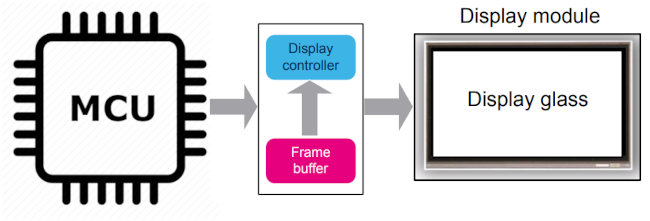
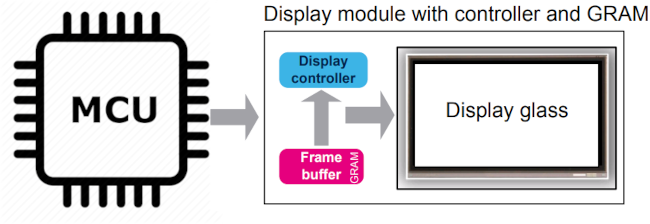
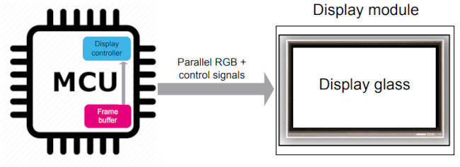
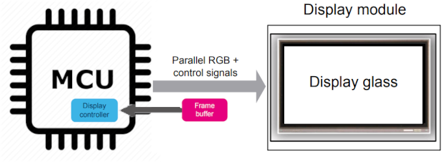
Display controller is continuously “refreshing” the display, by feeding the horizontal and vertical pixel data repeatedly from the frame buffer to the display glass 60 times per second (60 Hz). The display controller can be either embedded in the display module or in the MCU.
Display glass is driven by the display controller and is responsible to display the image that is
composed of a matrix of pixels. A display is characterized by:
- is defined by the number of pixels of the display that is represented by
horizontal (pixels number) x vertical (lines number). - Color depth: defines the number of colors in which a pixel can be drawn. It is represented in bits per pixel (bpp). For a color depth of 24 bpp (that can also be represented by RGB888) a pixel can be represented in 16777216 colors.
- Refresh rate (in Hz): is the number of times per second that the display panel is refreshed.

Display module embedded controller and GRAM

Display module without controller nor GRAM

Display module without controller nor GRAM, and with external GRAM
Display Interface Standards
Several display interfaces are used to connect the MCU to the display module. The Mobile Industry Processor Interface (MIPI) Alliance has standardized several of these interfaces:
MIPI Display Bus Interface (MIPI-DBI)
MIPI-DBI is used to interface with displays that have an integrated GRAM. It includes three types of interfaces:
-
Type A: Based on the Motorola 6800 bus.
-
Type B: Based on the Intel 8080 bus.
-
Type C: Based on the SPI protocol.
MIPI-DBI allows the MCU to update the pixel data in the display's local GRAM, reducing the bandwidth required for real-time data transfer.
MIPI Display Parallel Interface (MIPI-DPI)
MIPI-DPI standardizes the interface through a TFT controller, typically using 16-bit to 24-bit RGB signaling with synchronization signals (HSYNC, VSYNC, EN, and LCD_CLK). This interface is used for displays without a framebuffer, requiring the MCU to stream pixel data in real-time. While this provides excellent real-time performance, it demands high bandwidth from the MCU.
MIPI Display Serial Interface (MIPI-DSI)
MIPI-DSI reduces the number of lines required to interface with a display by using a high-bandwidth multilane differential link. It encapsulates DBI or DPI signals and transmits them through the D-PHY physical layer. This interface is ideal for high-resolution displays and mobile devices where minimizing the number of connections is crucial.
Conclusion
Generating graphics on TFT LCD displays involves a combination of hardware and software components working together to create and display images. Understanding the underlying technology, such as the operation of TFT LCDs and the role of the framebuffer and display controller, is essential for designing effective display systems. Different methods, from software-based rendering to hardware acceleration and external graphics controllers, offer various trade-offs in terms of performance, complexity, and cost. By leveraging the appropriate techniques and interfaces, electronic engineers can create efficient and visually appealing display solutions for a wide range of applications.
As display technology continues to evolve, staying informed about the latest advancements and standards, such as those developed by the MIPI Alliance, will be crucial for designing cutting-edge products. Whether you're developing a simple embedded system or a complex multimedia device, a solid understanding of graphics generation on TFT LCDs will help you achieve your design goals. For further reading, here is an example of driving 7" TFT LCD with STM32 MCU.
