Using TFT Touch Screen - Best Practices
TFT LCD touch displays are becoming more prevalent every day, in devices that range from consumer electronics to industrial and medical equipment. While design concepts for the use of TFT touch displays are well established, engineering and product design teams often come up against problems that are hard to solve. Following best practices on how to use TFT LCD touch screen can reduce a lot of "hair-pulling".
TFT LCD Touch Screen Installation Best Practices
- Make sure there is enough space (with cushion) between product housing and the TFT LCD screen.
- When mounting TFT LCD module, make certain that it is free from twisting, warping and bending.
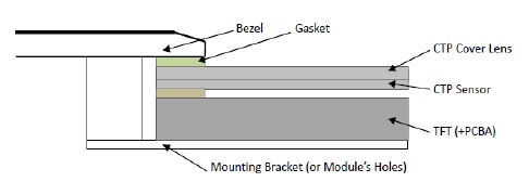
CTP Mounting with bezel

- The bezel window should be bigger (>0.5mm) than the Capacitive Touch Panel active area.
- Insulated gasket (0.5~1mm) should be installed between bezel and the CTP surface.
- Additional back support bracket is recommended for slim type TFT LCD display.
CTP Surface Mounting

- Double side adhesive is used to affix TFT LCD display in the countersink area.
- A gap (>0.3mm) is recommended, between product housing and LCD cover lens.
- When needed (e.g. TFT touch screen without mounding structure), backside support with gasket should be used.

- If additional cover lens is needed, engineer should re-check CTP specification about the acceptable material and thickness.
- 0.2~0.3mm gap is needed between cover lens and the TFT LCD surface.
- The cover lens window should be bigger (>0.5mm) than TFT touch screen's active area.
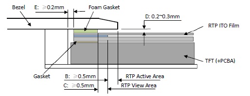
RTP Mounting

- A 0.2~0.3mm gap is needed between bezel and TFT LCD touch screen surface.
- Bezel should cover TFT LCD screen view area at least 0.5mm (B), to prevent user pressing RTP ITO Film connection area.
- Leave a 0.2~0.3mm gap between bezel side wall and the side of TFT touch display.
Grounding Design Best Practices
If the applied ground approach for a device equipped with a TFT touch display doesn’t follow best practices, a variety of issues can arise. Common challenges associated with grounding:
- Poor noise immunity, where interference negatively affects device operation
- Long-term drift, where shifts in voltages degrade performance of the display over time
In general, there are two key considerations: keeping ground connections as short as possible, and keep impedance to a minimum. This requirement is particularly critical in ground connections between display housing and touch controller. The diameter of the ground connection also has an effect, though it is less important than length.
Another important attention for grounding design is to avoid ground loops. Star topology for ground distribution, can avoid a situation where two points that are both intended to be at ground, have a potential between them.
Any floating conductive parts near touch sensor can cause erratic behavior in touch function. So they all should the same ground potential as the touch controller.
Conclusion
To address those issues, you need to follow best practices, including physical device assembly and grounding design. And those are just the top challenges, engineer will encounter a range of additional challenges, like longevity, slim design, and so on. Partnering with a hardware provider like Topway, who can advise you at every step along your path to market, is critical. With deep bench of expertise and 20+ years experience on TFT LCD industry, Topway offers you that guidance and ability to speed your time to market.
