How to implement LCD display resistive touch function
As smart phone leading the touch screen trend, more and more applications like medical LCD display, industry TFT display are embedding touch panels into the LCD screen. There are several LCD touch screen implementations in the market. We are using the simplest 4-wire resistive touch as example, to explain the basic of LCD touch screen implementation.
4-Wire Resistive Touch
AD7843 from Analog Device is a common 4-wire resistive touch panel controller. We are using it to support a resistive LCD touch screen.
Application Target and Platform Consideration
- Most of industry and instrument applications with touch screen are for menu selection and touch button function. High resolution reading from touch panel is not necessary.
- For a LCD display around 7" in size, a 4-bit resolution should be good enough (16x16 touch areas can be defined)
- AD7846 provides 12-bit or 8-bit A/D resolution. It's more than enough for our example
Understand AD7843 Operation
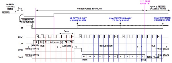
The diagram below shows a full AD7843 operation flow (single acquire operation). Based on that, engineers can design their program's operation sequence. (For continue sampling, please refer to AD7834 datasheet)
Communication Packet
- One packet contains 24 (3x8) clock pulse (DCLK)
- Communication starts after /CS=0 and the first DIN=1(start bit, S) latched into AD7843
- First 8 DCLK is for command input(Host to AD7843) via DIN, rising edge trigger
- Next 16 DCLK is for A/D result output (AD7843 to Host), data will be ready for the host after falling edge of DCLK (DCLK=0 provides a valid bit output at DOUT)
- For AD7843 configuration only, communication could be terminated after the 8th DCLK, using /CS=1
- For 8-bit sampling (setting MODE=1), communication could be terminated after the 16th DCLK, using /CS=1
- For 12-bit sampling (setting MODE=0), communication could be terminated after the 24th DCLK, using /CS=1
About /PENIRQ signal
- /PENIRQ is an "open collector" output signal. It may be necessary to add a pull up resistor (e.g. 10k) for the host
- On powering on, AD7843 provides /PENIRQ output, the output can be disabled by setting config bit PD0=1
- /PENIRQ reflects "touched" status. 1: not touched; 0: being touched
- After the "S" inputted, /PENIRQ will not function any more. At the 4th DCLK and after, changes to Hi. /PENIRQ resumes to normal function (command setting PD0=0)
- /PENIRQ is not related to /CS signal
AD7843 I/O routine
- The program inputs an 8-bit command and outputs an 8-bit A/D result
- Each bit is written at DCLK rising edge
- Each bit is read at DCLK=0
- All read/write finished at 16th DCLK and use /CS=1 to terminate communication
- 8 dummy DCLK are added to ensure /PENIRQ function normally after the routine
uchar TP_IO8(uchar Command)
// send a command and return 8bit conversion result
// Command bits(MSB to LSB): S,A2,A1,A0,MODE,SER/DFR,PD1,PD0
{
uchar i;
temp=Command; // copy the command to bit accessible variable
temp_b3=1; // set the MODE to 8bit only
TP_DOUT=1; // pull up for read
TP_DCLK=0; // prepare for data trans transfer
_TP_CS=0; // select the touch panel IO
for(i=0;i<8;i++) // write command with 1st to 8th DCLK
{
TP_DIN = temp_b7; TP_DCLK=1; TP_DCLK=0;
temp=temp<<1;
}
// delayms(1); // delay for 12bit conversion
for(i=0;i<8;i++) // read data
{
temp=temp<<1;
TP_DCLK=1; TP_DCLK=0; temp_b0=TP_DOUT;
}
_TP_CS=1;
for(i=0;i<8;i++) // PenIrq re-enable at 21st CLK
{ // thus 8 dummy clock provided
TP_DCLK=1; TP_DCLK=0;
}
return(temp);
}
Application Flow Example
- Use /PENIRQ to ensure touch panel is "being touched"
- Get X and Y A/D result (keep upper 4 bits)
- Delay for de-bouncing
- Again, use /PENIRQ to set touch panel is "being touched"
- Get X and Y A/D result (keep upper 4 bits)
- Delay for de-bouncing
- Once again, use /PENIRQ to ensure touch panel is "being touched" and compare the last two sets of results
- It the results are the same, we can confirm the touch panel is functioning correctly, and reliable result is given out
- Based on this result, we could display a box or do a response on screen.
void WzitTouchAndResponse(void)
{
uchar x, y;
uchar i, j ;
uchar Verified_AD; // flag for verified A/D
Verified_AD=0;
while (Verified_AD==0)
{
while(_TP_PENQ) // ensure it is touched then start AD
{
}
i = TP_IO8(0xd8)>>4; // X-Ch, 8bit, LoPw, with PenInt
j = TP_IO8(0x98)>>4; // Y-Ch, 8bit, LoPw, with PenInt
delayms(50); // de-bouncing
while(_TP_PENQ) // ensure it is touched then start AD
{
}
x = TP_IO8(0xd8)>>4; // X-Ch, 8bit, LoPw, with PenInt
y = TP_IO8(0x98)>>4; // Y-Ch, 8bit, LoPw, with PenInt
delayms(50); // de-bouncing
if ((i==x) && (j==y) && (!_TP_PENQ)) // ensure two results are the same
{ // and still touching
Verified_AD=1;
}
}
Box20x15(x, y, touch_Mark);
}
Above program could be further improved to fit actual application.
Summary
Above example is for low resolution touch application, its logic flow could be used in higher resolution application. Also, to support touch operation, it is not always necessary to do tones calculation. A reasonable logic flow could simplify the whole operation.