TFT LCD LVDS Interface Guide (2026): VESA vs JEIDA, Pros, and Industrial Design Best Practices
✅ LVDS Quick Facts for Engineers
- Signal Type: Low-voltage differential (~350mV swing)
- EMI Immunity: Excellent (common-mode noise rejection)
- Max Cable Length: 1.5–3 meters (with 100Ω twisted pair)
- Typical Use Cases: Industrial HMI, medical displays, outdoor signage
- Format Critical: VESA vs JEIDA mismatch = color distortion
- 1080p Support: Requires dual-channel LVDS
- MCU Integration: Needs RGB-to-LVDS bridge IC (e.g., SN75LVDS83A)
Recent advancements in industrial automation, smart factories, and medical equipment have demanded more bandwidth and reliability from display interfaces than ever before. Traditional point-to-point physical layer interfaces often struggle with the high data rates required for modern, high-resolution screens without falling victim to electromagnetic interference (EMI).
To overcome the physical layer bottleneck, engineers frequently turn to LVDS.
What is LVDS?
While commonly referred to as a protocol, LVDS is strictly a physical layer signaling standard (TIA/EIA-644). The actual video protocol used to map the RGB data (such as VESA or JEIDA formats) across this physical layer is typically FPD-Link.
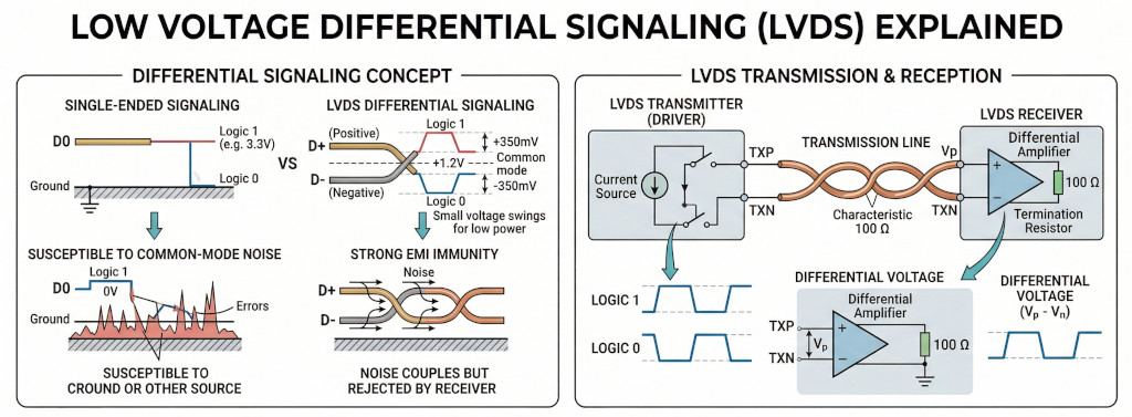
LVDS (Short for Low Voltage Differential Signaling), a low noise, low power, low amplitude general purpose signaling method that solves the bottleneck problems while servicing a wide range of application areas. LVDS supports high-speed (gigabits per second) data transmission over copper wires, making it ideal for robust B2B and industrial display applications.
Low Voltage - LVDS technology is not dependent on a specific power supply, e.g. +5V. Which means it is easy to migrate your design to lower supply voltages, such as +3 volts or even lower, while still maintaining the same signaling levels and performance.
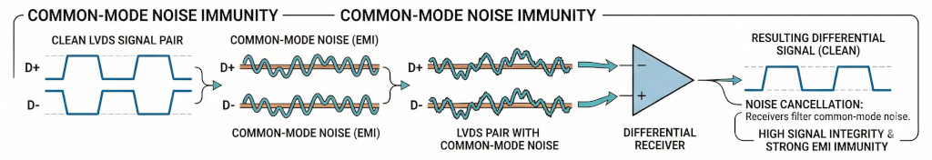
Differential Signaling - LVDS uses a dual wire system, running 180 degrees of each other. Normal digital I/O works with, say 5 volts as a high (binary 1) and 0 volts as a low (binary 0). When using a differential, you add a third option (-5 volts), which provides extra level to encode data. Noise coupled onto the interconnect is seen as common mode modulations by the receivers and is easily filtered out. The receivers respond only to differential voltages. That's why LVDS interface has strong EMI immunity, and high signal integrity.
Why LVDS is Widely Used in Industrial TFT LCDs
When designing HMIs (Human-Machine Interfaces) or ruggedized equipment, choosing the right interface is critical. LVDS is one of the most widely adopted interfaces in industrial displays due to its robustness and scalability.
Key Advantages of LVDS
- Excellent EMI Resistance: Because it uses differential signaling, LVDS is highly resistant to the electrical noise generated by heavy machinery, motors, and industrial power supplies. When external noise hits the cable, it affects both wires equally (common-mode noise). Since the receiver only looks at the difference between the wires, the noise is canceled out.
- Longer Transmission Distances: Compared to standard TTL/RGB interfaces which are limited to very short cable runs (typically < 15cm), LVDS can transmit data over much longer cables (up to several meters depending on the setup) without signal degradation.
- Lower Power Consumption: The low voltage swing(~350mV) requires less power, which minimizes heat generation inside tightly sealed industrial enclosures.
- Fewer Wires: Serializing the data reduces the pin count and wire count significantly, leading to simpler, more reliable connectors and reduced cable bulk.
Limitations of LVDS
- Not Native to All Microcontrollers: Many entry-level or older MCUs do not feature native LVDS outputs. Driving an LVDS display with these requires a dedicated RGB-to-LVDS bridge IC(such as SN75LVDS83A), increasing BOM (Bill of Materials) cost and PCB footprint.
- Cable Quality Sensitivity: Requires twisted-pair impedance-controlled cables(like Cat5e or dedicated LVDS cables) for optimal performance.
When to Use LVDS Interface
Use LVDS when you are building:
- Industrial HMI systems: Industrial environments are "electrically noisy" due to high-voltage motors, relays and switching power supplies. LVDS uses differential signaling, common-mode noise can be easily filtered out.
- BESS (Battery Energy Storage Systems) and PCS (Power Conversion System): These devices handle high-voltage DC-to-AC power conversion, high frequency switching (IGBT). Such processes generate lots electrical noise. LVDS is borned to survive these challenge working environments.
- Medical equipment: LVDS interface uses very small voltage swing (typically 350mV), it consumes significantly less power than older high-swing interfaces. Thus LVDS interface produce significant less electrical noise. This is very important in medical settings.
- Outdoor high-brightness displays (≥ 800 nits): High brightness displays have high power backlights, which are generating certain amount heat. LVDS's lower power consumption help reducing the whole system's thermol stress.
When NOT to Use LVDS
Avoid LVDS if:
- You need ultra-high resolution (>4K) → consider eDP
- Cable length is extremely short (<10 cm) → RGB may be sufficient
- BOM cost must be minimized aggressively
LVDS vs RGB vs SPI vs MIPI vs eDP
| Interface | Speed | EMI Resistance | Cable Length | Complexity | Typical Use Case |
|---|---|---|---|---|---|
| LVDS | High | Excellent | Medium - long | Medium | Industrial displays, HMI |
| SPI | Very low | Moderate | Short | Very low | Small displays, embedded UI |
| RGB (TTL) | Low | Poor | Very short | Low | Entry-level TFTs |
| MIPI DSI | Very High | Moderate | Short | High | Smartphones, tablets |
| eDP | Very High | Good | Medium | High | Laptops, high-res panels |
For in-depth comparison and picking the right display interface, check out this interface selection guide.
What is the difference between VESA and JEIDA LVDS formats?
When connecting an LVDS TFT LCD, matching the data format between the host controller and the display is crucial. An improper match will result in distorted, "solarized," or completely scrambled colors. There are three main flavors, when it comes to LVDS interfaces for TFT LCD connectivity: 18-bit data format, 24-bit VESA data format and 24-bit JEIDA data format. Table below is the three major TFT LVDS signal mapping pinout used in the industry.
| Channels Formats | ||||
|---|---|---|---|---|
| 18bit | 24bit (VESA) | 24bit(JEIDA) | ||
| LVDS Channels | RX0+/- | R0~R5,G0 | R0~R5,G0 | R2~R7,G2 |
| RX1+/- | G1~G5,B0,B1 | G1~G5,B0~B1 | G3~G7,B2~B3 | |
| RX2+/- | B2~B5,HS,VS,DE | B2~B5,HS,VS,DE | B4~B7,HS,VS,DE | |
| RX3+/- | Not use | R6,R7,G6,G7,B6,B7 | R0,R1,G0,G1,B0,B1 | |
| Color Depth | 262K Colors | 16.7M Colors | 16.7M Colors | |
| Quick Facts | Standard for basic industrial GUIs requiring standard color depth. | If connected to a JEIDA display, the image will look washed out or have strange color gradients. | Widely adopted in modern industrial TFTs. Often cross-compatible with 18-bit panels. | |
For a single-channel 24-bit LVDS interface, the difference between VESA and JEIDA bit assignments, comes down to where they place the Most Significant Bits (MSBs) and Least Significant Bits (LSBs) of data.
1. The VESA Format
VESA maps the data in a more straightforward, sequential order, but sacrifices compatibility. It fills the first three lanes (RX0, RX1, RX2) sequentially starting with the lowest bits. This forces the Most Significant Bits (MSBs)—the highest two bits (R6, R7, G6, G7, B6, B7)—onto the 4th data lane (RX3).
The Result: The most critical data for defining image's color and contrast lives on RX3. If we plug a 24-bit VESA host into an 18-bit panel, the panel drops RX3. Because it loses the Most Significant Bits, the image will look heavily distorted, often described as "solarized," "washed out," or appearing like a thermal camera feed.
2. The JEIDA Format
JEIDA was designed with backward compatibility in mind. It places the Least Significant Bits (LSBs)—the lowest two bits of red, green, and blue (R0, R1, G0, G1, B0, B1)—on the 4th data lane (RX3).
The Result: The first three lanes (RX0, RX1, RX2) carry the core color data (the MSBs). If you plug a 24-bit JEIDA host controller into an older or cheaper 18-bit display panel, the display simply ignores the RX3 lane. Because it still receives the Most Significant Bits, the image displays perfectly normally, just with a slightly reduced color depth (262K colors instead of 16.7M).
3. Compatibilty
| Host Output Format | ||||
|---|---|---|---|---|
| 18bit | 24bit (VESA) | 24bit(JEIDA) | ||
| TFT Input Format | 18bit | ✓ | X | ✓ |
| 24bit (VESA) | X | ✓ | X | |
| 24bit (JEIDA) | ✓ | X | ✓ | |
1. Wrongly feed 24bit-LVDS(JEIDA) signal to 24bit-LVDS(VESA) TFT Display Module.
2. Wrongly feed 24bit-LVDS(VESA) signal to 24bit-LVDS(JEIDA) TFT Display Module.
3. Wrongly feed 24bit-LVDS(VESA) signal to 18bit-LVDS TFT Display Module.
4. Wrongly feed 18bit-LVDS signal to 24bit-LVDS(VESA) TFT Display Module.

Dual Channels LVDS
Dual-channel LVDS is used for high-resolution displays (usually 1920x1080 and above). Because a single channel simply doesn't have the bandwidth to transmit that many pixels at a standard 60Hz refresh rate. In a dual-channel LVDS setup, data lines are defined by splitting the display's pixel data into two separated streems. The system sends Pixel 1 down the Odd channel, Pixel 2 down the Even channel, Pixel 3 down the Odd channel, and so on.
Channel 1: The Odd Channel (Usually labeled "O" or "A")
This channel carries the odd-numbered pixels on the screen (Pixel 1, 3, 5...).
- RXO0- / RXO0+ (Data Lane 0)
- RXO1- / RXO1+ (Data Lane 1)
- RXO2- / RXO2+ (Data Lane 2)
- RXO3- / RXO3+ (Data Lane 3)
- RXOC- / RXOC+ (Odd Clock pair)
Channel 2: The Even Channel (Usually labeled "E" or "B")
This channel carries the even-numbered pixels on the screen (Pixel 2, 4, 6...).
- RXE0- / RXE0+ (Data Lane 0)
- RXE1- / RXE1+ (Data Lane 1)
- RXE2- / RXE2+ (Data Lane 2)
- RXE3- / RXE3+ (Data Lane 3)
- RXEC- / RXEC+ (Even Clock pair)
If you are using a lower-spec 6-bit panel (262K colors), Data Lane 3 (RXO3 and RXE3) will be missing or left unconnected, leaving you with 3 data pairs and 1 clock pair per channel.
Engineer Insights
How to Connect an LVDS TFT LCD to an MCU
MCU (RGB Output)
↓
RGB-to-LVDS Bridge IC
↓
LVDS Cable
↓
TFT LCD Panel
Here is a technical white paper, about how to drive an LVDS TFT display.
Common IC Solution
TI SN75LVDS83A (single-channel)
Dual-channel required for higher resolutions (e.g., 1920×1080)
Design Guidelines for LVDS Systems
Hardware Design Best Practices
- Use 100Ω differential impedance routing
- Keep trace length matched (±5 mil tolerance)
- Minimize stubs and vias
- Use proper shielding for cables
How to Determine Whether Dual-channel LVDS is needed
The main difference between single and dual-channel LVDS is hardware capacity, like a two-lane highway allows more car passing through than a single lane one. Calculating the data bandwidth for an LVDS interface requires determining the Pixel Clock first. The pixel clock defines how many pixels are transmitted per second, which we then multiply by the color depth to find the total data payload bandwidth.
1. Calculate Total Pixels per Frame
Displays need time to process rows and frames, known as the blanking interval. We must add this overhead to the active resolution.
Total Pixels = (W + Wblank) × (H + Hblank)
2. Calculate Pixel Clock
Multiply the total pixels per frame by the refresh rate (frames per second).
Pclk = Total Pixels × Refresh Rate
3. Calculate Data Bandwidth
Multiply the pixel clock by the color depth (Bits Per Pixel).
Bandwidth = Pclk × Color Depth
LVDS Bandwidth Calculator
FAQ
1. What is LVDS used for?
LVDS is used for high-speed, high noise enduring, low-noise data transmission in displays, especially in industrial, automotive, and medical systems.
2. Is LVDS better than RGB?
Yes, for industrial use. LVDS provides better EMI resistance, longer cable distance, and lower power consumption than RGB.
3. What is the difference between VESA and JEIDA?
VESA and JEIDA differ in how pixel data bits are mapped. A mismatch results in incorrect color rendering.
4. Can STM32 drive an LVDS display?
Not directly. STM32 typically requires an RGB-to-LVDS bridge IC to interface with LVDS panels.
5. Can LVDS do 1080p?
Yes. You need dual-channel LVDS. A standard Single-Channel LVDS interface typically has a maximum pixel clock of around 85MHz. But 1080p @ 60Hz requires a pixel clock of approximately 148.5MHz.
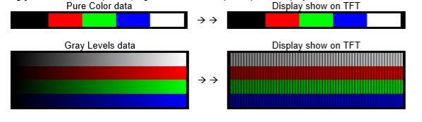
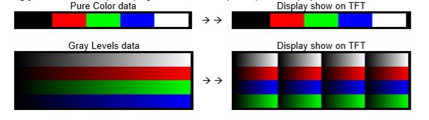
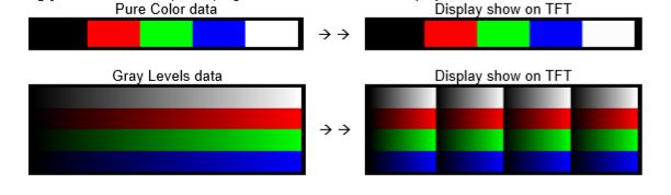
6. How do I tell if my LVDS data signals and TFT display's LVDS interface are mismatched?
Showing a gray level bar on the TFT display will help you uncover the issue easily. See this post, for detail explanation.
Partner with Display Experts
Topway produces a wide range of LVDS TFT LCD displays, available in various screen sizes, resolutions, and brightness levels. Whether you are building an industrial control panel or a medical device, our engineering team can help you select the exact specifications for your environment.
Contact Topway Display today to discuss your project requirements or request an LVDS module sample.